
Aviation Ground Support Equipment: Categories, Uses and Sourcing

Aviation ground support equipment (GSE) is the fleet of vehicles, machinery and tooling that services aircraft on the ground – at the gate, on remote stands and inside maintenance hangars. It falls into five broad groups: power and starting, aircraft movement, servicing, loading and passenger handling, and engine and component handling. Every minute of a turnaround and every hangar visit depends on it. The sourcing question – buy, rent or lease – gets answered differently for a baggage tractor than for an engine stand, and that difference shapes the whole market.

Ground support equipment at a glance

Any airport ramp or maintenance hangar runs on some mix of five equipment groups.

CategoryTypical equipmentPrimary role
Power and startingGround power units (GPU), air start units (ASU), pre-conditioned air unitsElectrical power, start air and cabin climate while engines are off
Aircraft movementPushback tugs, towbarless tractors, towbars, wheel chocksPositioning aircraft without running their engines
ServicingFuel trucks and hydrant dispensers, lavatory and water trucks, de-icing rigs, catering trucksFluids, waste, cabin supplies and winter operations
Loading and passenger handlingBelt loaders, container and pallet loaders, cargo dollies, baggage tractors, stairs, apron busesMoving cargo, baggage and passengers between terminal and aircraft
Engine and component handlingEngine stands and cradles, bootstrap kits, aircraft jacks, maintenance platformsEngine changes, transport, storage and heavy maintenance access
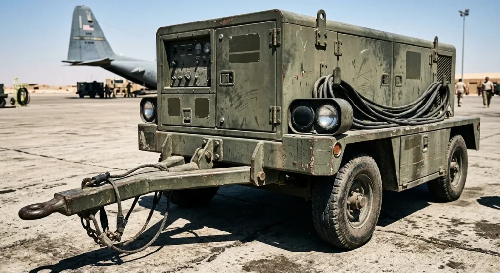
Mobile ground power unit connected to an aircraft

What is aviation ground support equipment?

Aviation ground support equipment covers everything that services an aircraft while it is not flying: the machinery parked around a jet at the gate, the tooling in the hangar, and the vehicles shuttling between them. The term spans commercial airlines, cargo operators, business aviation, MRO facilities and the military, where the same functions appear in ruggedized form. An aircraft earns nothing parked at a gate, so every piece of GSE exists to shorten, secure or enable its time on the ground.

GSE splits into powered and non-powered equipment. Powered GSE has its own drive or power source – a pushback tug, a diesel or electric GPU, a catering truck. Non-powered GSE has none: towbars, chocks, dollies, jacks and engine stands are positioned by hand or towed. Non-powered does not mean unregulated – a loaded engine stand or a set of aircraft jacks is load-rated, inspected and maintained with the same seriousness as any vehicle on the ramp, to design and test standards maintained by the SAE AGE committee.

TypeExamplesCharacteristics
Powered GSEPushback tugs, GPUs, ASUs, belt loaders, fuel and catering trucks, apron busesOwn engine or electric drive; needs trained operators, fueling or charging, and preventive maintenance
Non-powered GSETowbars, chocks, cones, cargo dollies, baggage carts, engine stands, jacksNo drive system; towed or positioned manually; lower upkeep but still load-rated and inspected

The five GSE categories in detail

1. Power and starting equipment

Aircraft systems need power long before and after the engines run. Ground power units feed an airliner’s primary 115/200V three-phase AC system at 400 Hz and usually offer a 28V DC output alongside it – the standard supply for smaller aircraft – from either a mobile diesel unit or a fixed gate installation. Air start units deliver compressed air to spin up a turbine engine when the aircraft’s own APU is inoperative or its use is restricted. Pre-conditioned air units keep the cabin at temperature without burning fuel. The unusual 400 Hz frequency is an aviation legacy standard: it allows onboard electrical components to be smaller and lighter than at household frequencies, so ground equipment adapted to the aircraft rather than the other way around. Together, these units let an aircraft stay fully alive at the gate with its engines and APU shut down, saving fuel and cutting ramp noise – many airports now restrict APU running time at the gate for exactly that reason.

2. Aircraft movement equipment

Some aircraft can technically back up on reverse thrust – powerback was once routine on a few types – but ramp procedures all but universally prohibit it, and taxiing in congested gate areas is expensive and risky in any case. Movement GSE fills the gap. Conventional pushback tugs connect to the nose gear through a towbar; towbarless tractors lift and secure the nose wheel on a cradle, which speeds up hookup and takes towbar handling out of the job – always within the towing limits published for each aircraft type. Heavier tow tractors relocate aircraft over longer distances – from a remote stand to the hangar, for example – while chocks, cones and towbars round out the non-powered side of the category. Towing is a deliberate, low-speed operation with wing walkers watching clearances, because a widebody’s wingtips extend far beyond what the tug driver can judge from the cab.

3. Servicing equipment

Servicing GSE handles fluids and consumables. Fueling is done either by tanker truck or by a hydrant dispenser that connects the aircraft to an underground fuel network. Separate potable water and lavatory service trucks are kept strictly apart for hygiene reasons. Catering trucks with scissor-lift bodies raise galley carts to cabin door height. In winter operations, de-icing rigs spray heated fluid over wings and control surfaces from a raised, articulated boom – a servicing task with a direct and immediate safety role, performed against the clock because de-icing fluid protects the aircraft only for a limited holdover time before departure.

4. Loading and passenger handling equipment

Belt loaders move loose baggage into narrow-body holds, while wide-body freight travels in unit load devices (ULDs) – standardized containers and pallets that lock into the aircraft’s cargo floor. Dedicated container loaders raise entire ULDs to sill height on scissor platforms and roll them aboard on powered conveyor decks. Baggage tractors pull trains of carts and dollies between the sorting hall and the aircraft. On the passenger side, mobile stairs and apron buses take over wherever a jet bridge is not available, keeping remote-stand operations moving.

5. Engine and component handling equipment

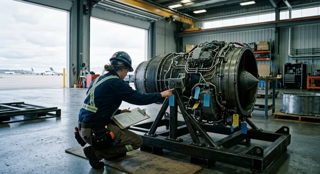
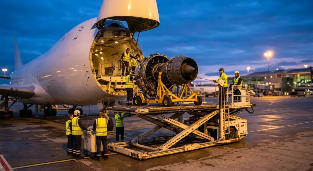
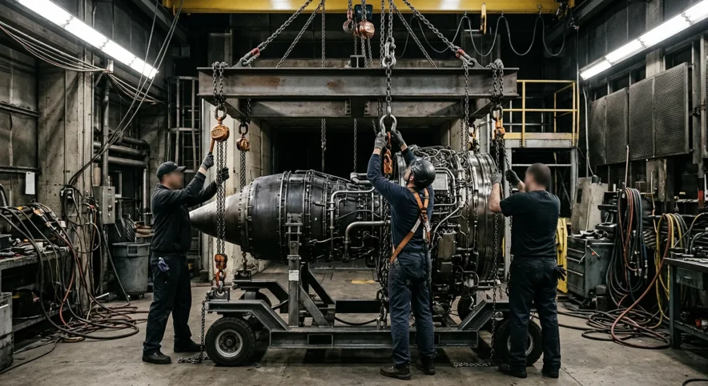
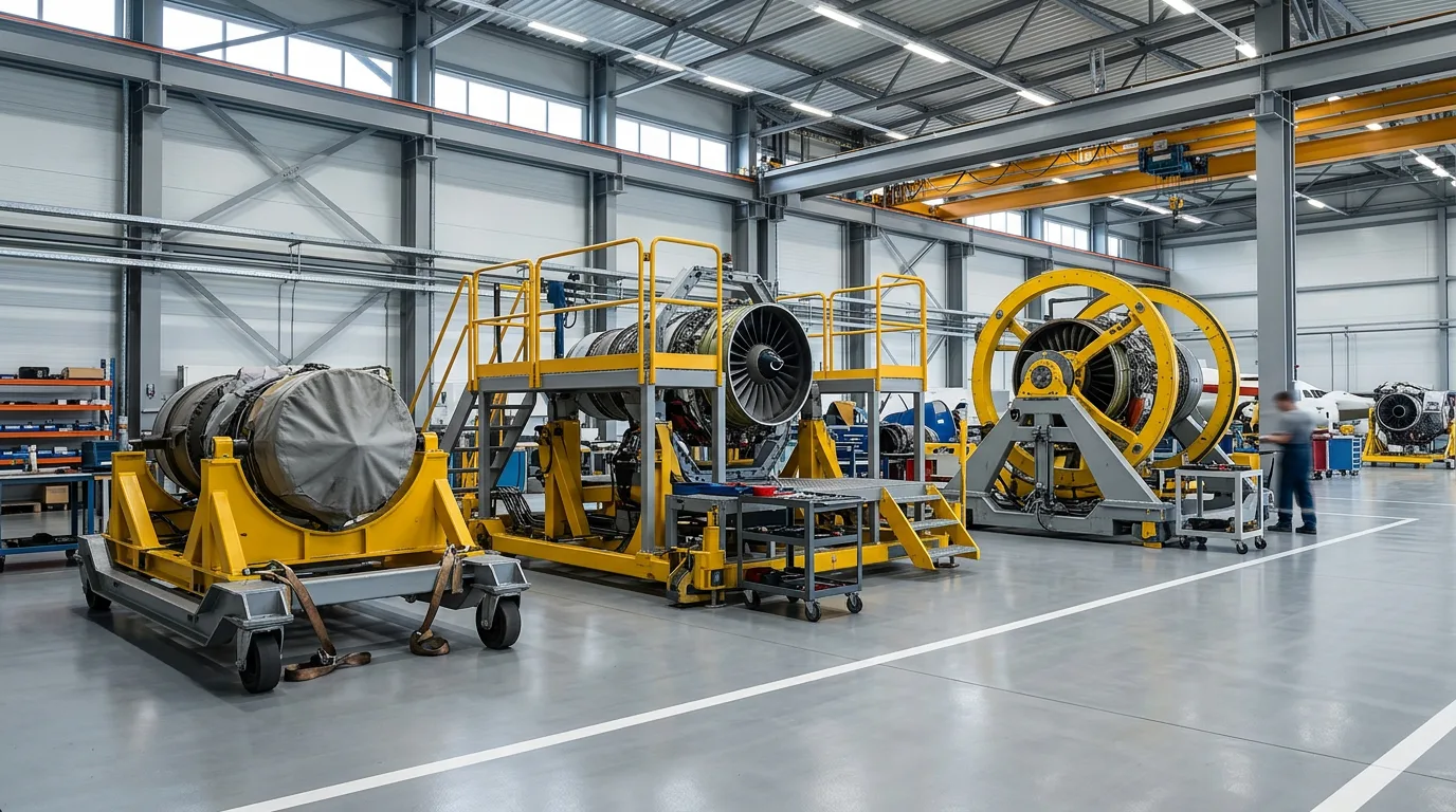
Passengers never see this category, but heavy maintenance runs on it. Aircraft jacks lift the airframe for gear swings and weighing. Maintenance platforms give mechanics stable access to tails and pylons. And engine stands – wheeled cradles engineered for a specific engine family – carry engines through changes, shipping and storage. A typical stand pairs a base frame with a cradle that grips the engine at manufacturer-approved mount points, often through shock-absorbing isolators that protect bearings from road and ramp vibration. During an engine change, a bootstrap kit – a set of hoists attached to the engine mounts and the pylon – lowers the engine onto its stand and lifts the replacement into position. Because each stand is built around one engine family’s mount points and center of gravity, fleets need the right stand for the right engine; our overview of aircraft engine stand types breaks the options down.

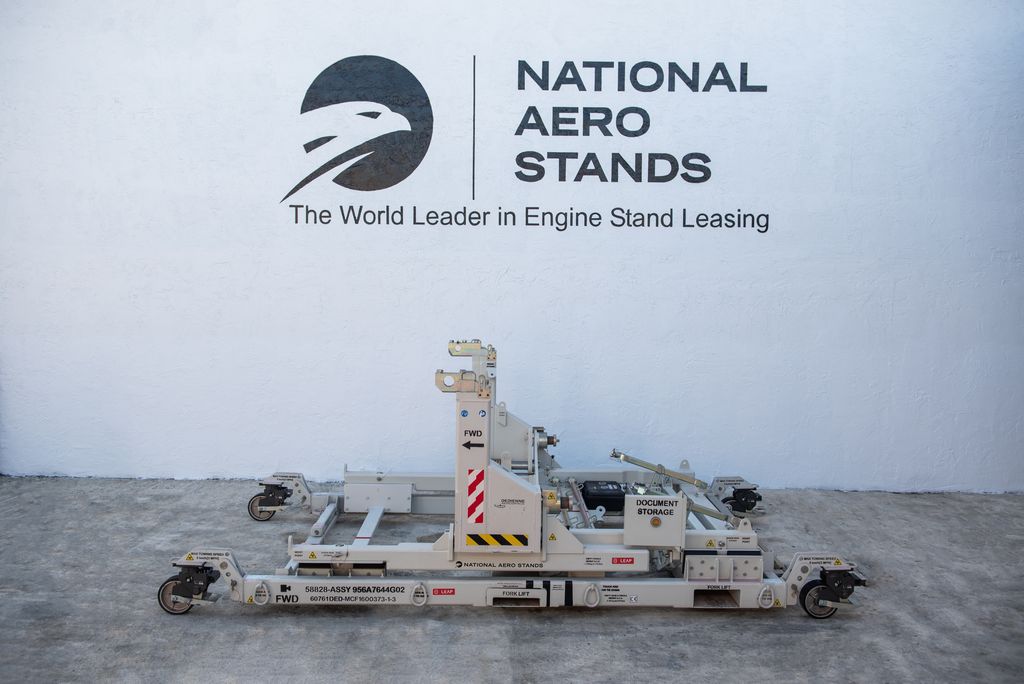
Planning an engine change or shipment? National Aero Stands rents and leases engine stands for CFM56, LEAP, Trent, GE90 and PW engines, available worldwide.

Towbarless pushback tractor gripping a nose wheel at dawn

How GSE drives the aircraft turnaround

During a standard turnaround, a dozen machines converge on one aircraft on a crowded airport apron, work in parallel for roughly half an hour and clear out before pushback. The faster and more predictably GSE moves through that sequence, the more flying an airline gets out of each airframe. The windows below are typical for a narrow-body turnaround; each airline’s ground operations manual sets its own.

TaskEquipment involvedApprox. window
Arrival: chocks, cones, ground power onChocks, cones, GPU or fixed gate powerFirst approx. 5 min
Passenger deboarding and boardingJet bridge or stairs, apron busesRuns through most of the turnaround
Baggage and cargo exchangeBelt loaders, baggage tractors, dolliesApprox. 5-35 min
FuelingHydrant dispenser or fuel truckApprox. 10-30 min
Cabin service: catering, water, lavatoryCatering trucks, water and lavatory trucksApprox. 10-30 min
Pushback and engine startPushback tug, ASU if requiredFinal approx. 5-10 min

A dead GPU or a tug stuck in maintenance does not just slow one task – it pushes the whole sequence right, and the delay propagates through the day’s schedule. That is why ground handling contracts increasingly specify equipment readiness levels alongside staffing, and why handlers track GSE utilization the way airlines track aircraft utilization: an idle loader is sunk cost, but a missing one is a delay code with the airline’s name on it.
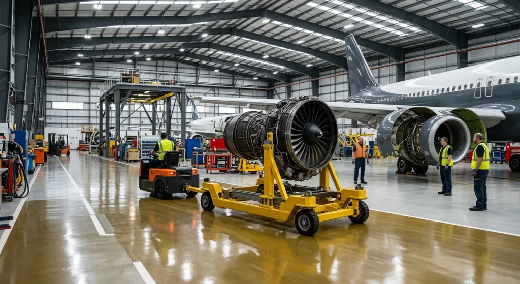
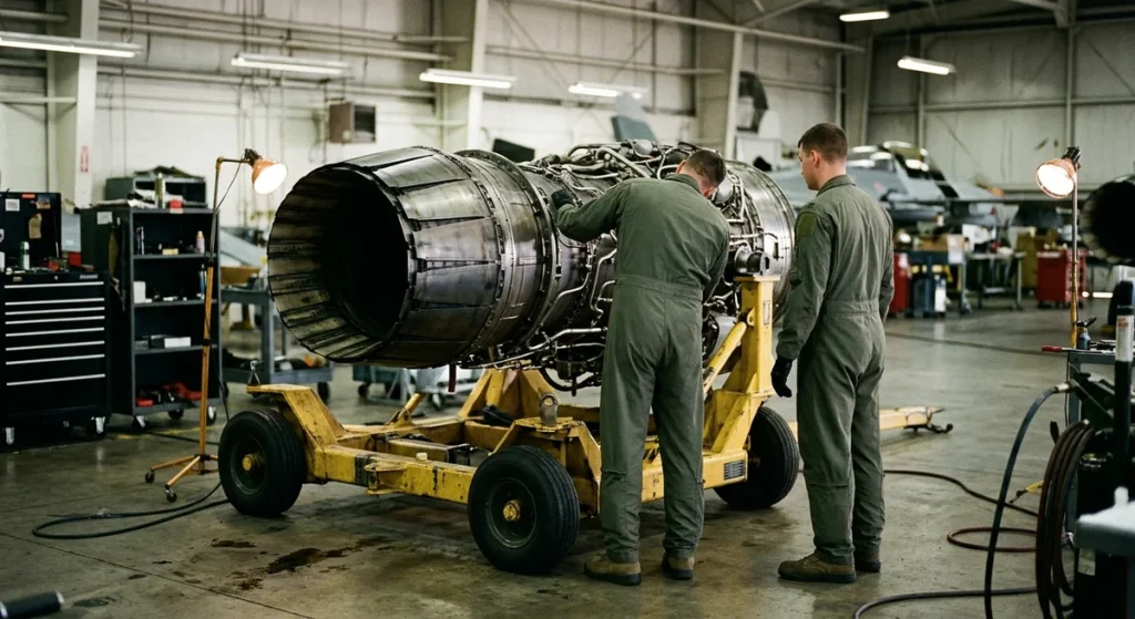
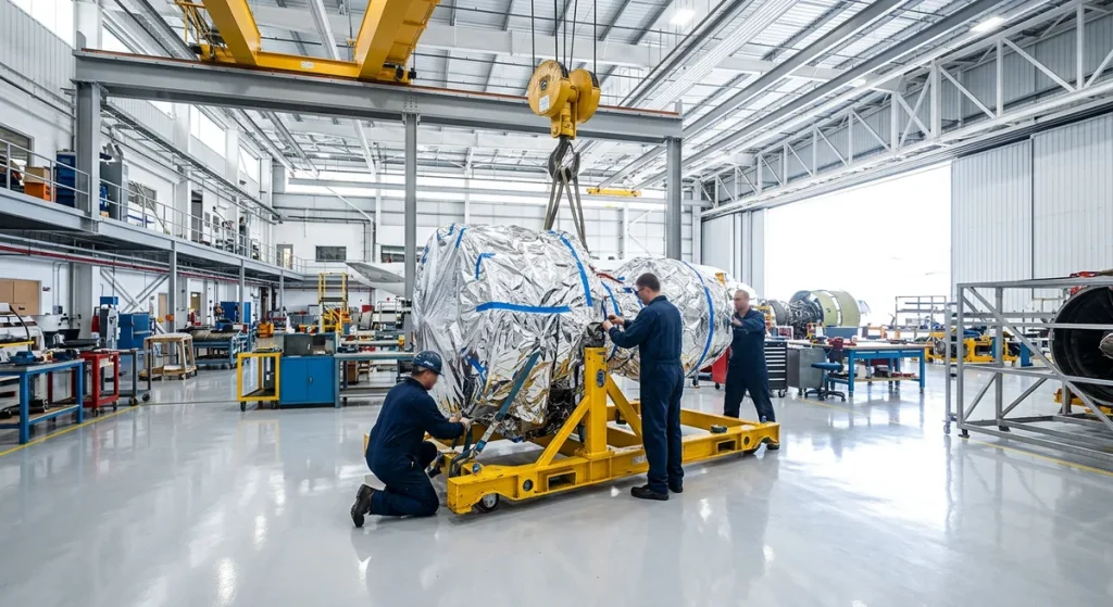
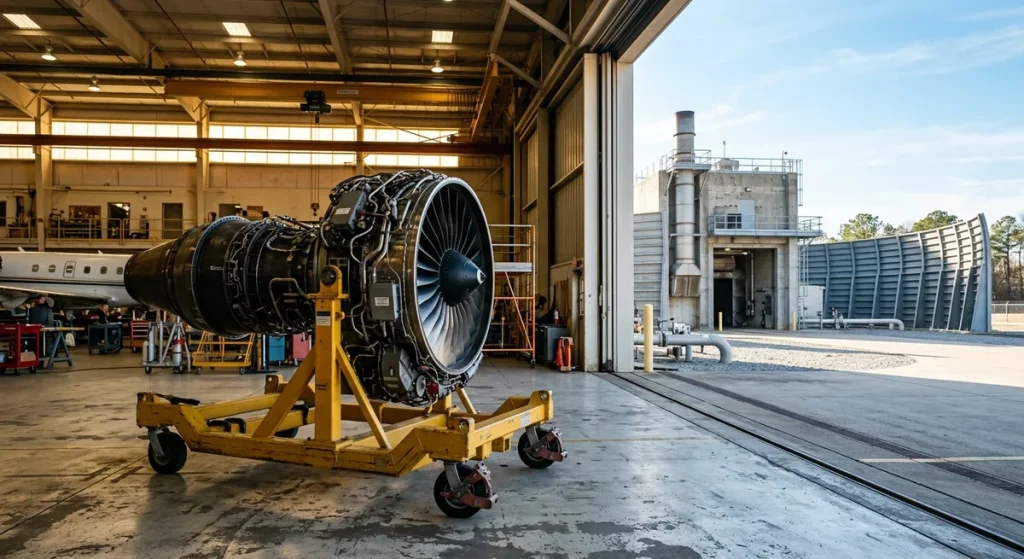
Turbofan engine on a wheeled stand towed through an MRO hangar

GSE in maintenance and MRO

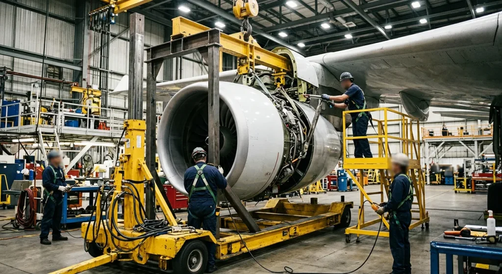
Away from the gate, GSE changes character: less about speed, more about precision and load handling. Hangar work – everything covered by MRO in aviation – leans on jacks, access platforms, component cradles and above all engine stands; in an EASA Part-145 organization that tooling is controlled and inspected under the same approval as the work itself. An engine change is the clearest example: the bootstrap kit lowers the engine from the pylon onto a stand, the stand carries it across the hangar or into a truck. Transport, storage and shop work are not always the same piece of hardware, though: at a shop visit the engine usually comes off onto the shop’s own build-up stand, and a rented transport stand goes back into the pool.

Engine stands therefore sit in a different procurement category than most GSE. A belt loader works every day; at many operators a Trent 700 stand may be needed twice a year, then urgently and immediately, while a large engine shop keeps its stands working week in, week out. That usage pattern often makes rental or leasing the better sourcing model for engine handling equipment, above all for low-frequency events, demand peaks and non-core engine types.

Military aviation ground support equipment

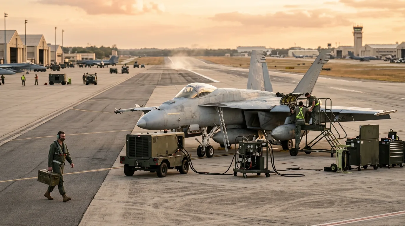
Defense operators use the same functional categories under a different set of constraints. Military aircraft ground support equipment – AGSE in US Army usage, while the US Air Force calls its equivalent AGE, for aerospace ground equipment – must survive rough handling, operate from austere or unpaved locations, and frequently be air-transportable itself. Mobile maintenance shelters, ruggedized power carts, tactical tow tractors and reinforced fuel and water trucks mirror their commercial counterparts with heavier construction and simpler field repair. Engine stands appear here too, built to military specifications for specific engines. We cover the category in depth in our guide to military aircraft GSE.

Lavatory and water service vehicles beside a parked aircraft

Electric GSE and the sustainability shift

Diesel still dominates the installed GSE base, but replacement purchases are increasingly electric; in the United States the FAA Zero Emissions Vehicles program funds airports converting their fleets. Baggage tractors, belt loaders and smaller pushback tugs went first because their duty cycles suit batteries: short runs, frequent idle periods, home base always nearby. Electric GPUs and larger tugs are following. Ramp crews breathe no exhaust at ground level, noise drops, and there are fewer moving parts to maintain; many airports now write emissions requirements into ground handling licenses. The trade-offs are real too – winter derating, charger uptime, batteries that age with every fast cycle – and charging points compete for the same scarce apron space as everything else, so electrification advances gate by gate rather than fleet-wide overnight. Over a unit’s working life, lower energy and maintenance costs offset the higher purchase price for many duty cycles, which shifts procurement decisions even where no regulation forces the issue.

Ramp safety around ground support equipment

Heavy machinery working within arm’s reach of a pressurized fuselage – metal or composite – is an inherently unforgiving environment. Ground damage from GSE collisions – a belt loader kissing a cargo door sill, a catering truck against the fuselage – is one of the industry’s persistent cost drivers, and much of it happens at low speed in good weather. Standard defenses include strict approach procedures, guide persons for reversing vehicles, speed limits on the ramp, and FOD (foreign object debris) discipline: a dropped bolt or a torn baggage tag on the apron can end up in an engine inlet, so equipment staging areas are kept clean and walked regularly.

Non-powered equipment has its own failure modes. An unsecured engine stand, an unrated lifting point or a jack on soft ground can damage an engine or injure a technician in seconds. Load ratings, inspection tags and securing protocols exist precisely because this category looks harmless and is not.

Buying, renting and leasing aviation ground support equipment

Sourcing strategy depends on utilization. Equipment used daily – tugs, loaders, GPUs – is usually bought new or used and run through a structured maintenance program. Buying new brings warranties and current emissions compliance; the used market cuts capital cost for operators who can absorb more maintenance risk. Equipment used episodically – engine stands above all – is more often rented or leased, so the cost appears only when an engine change, shipment or storage project actually happens.

Before any purchase or rental contract is signed, four checks matter:

  • Fleet compatibility: the equipment must match your aircraft and engine types – towing capacity, sill heights, mount points, load ratings.
  • Operating environment: climate, apron space and surface conditions decide between standard and ruggedized or compact units.
  • Versatility: equipment that serves several aircraft or engine types reduces total fleet size and idle assets.
  • Support and documentation: spares availability, service coverage, and current inspection and load-test records – especially for anything that carries an engine.

The equipment is rarely the expensive part. The expensive part is the aircraft standing still behind a missing tug – or an engine change on hold because the right stand is weeks away.

FAQ: aviation ground support equipment

What does GSE stand for in aviation?

GSE stands for ground support equipment: the vehicles, machinery and tooling used to service aircraft on the ground. It covers everything from pushback tugs, ground power units and fuel trucks to non-powered items such as chocks, towbars, jacks and engine stands. What are the main types of ground support equipment?

The usual industry breakdown runs to five groups: power and starting (GPUs, air start units), aircraft movement equipment (tugs, tractors, towbars), servicing equipment (fuel, water, lavatory, de-icing, catering), loading and passenger handling (belt and container loaders, stairs, buses), and engine and component handling (engine stands, jacks, platforms). What is AGSE?

AGSE stands for aircraft (or aviation) ground support equipment, an abbreviation used mainly in US Army aviation and parts of the aerospace industry; the US Air Force uses AGE (aerospace ground equipment) for the same category. In practice it covers the same categories as commercial GSE, in ruggedized and often air-transportable form – including engine stands built to military specifications. Are engine stands considered ground support equipment?

Yes. Engine stands belong to the engine and component handling category of GSE, alongside jacks, bootstrap kits and maintenance platforms. They are non-powered GSE: no drive system, but strict load ratings, engine-family-specific cradles and regular inspections, since a single stand carries an asset worth millions. What is the difference between powered and non-powered GSE?

Powered GSE has its own drive or power source – tugs, GPUs, belt loaders, fuel and catering trucks – and needs operators, fuel or charging, and preventive maintenance. Non-powered GSE, such as towbars, chocks, dollies, jacks and engine stands, is towed or positioned manually but remains load-rated and inspected. Who owns and operates GSE at airports?

It varies by airport and contract. Ground handling companies operate most gate equipment, airlines often own fleets at their hubs, airports provide fixed installations such as gate power, and MRO facilities keep their own maintenance GSE. Specialized items like engine stands are frequently rented from dedicated providers as needed.
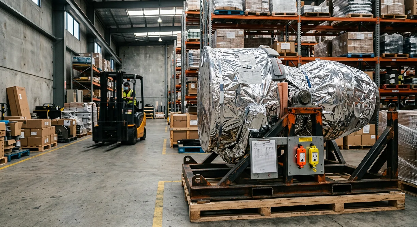

Aircraft Engine Shipping: The Process from Preservation to Handover

Aircraft engine shipping is a controlled, step-by-step process: preserve the engine, mount it on an approved shipping stand, prepare customs and export paperwork, book the move through a freight forwarder, monitor transit with shock and tilt indicators, and inspect the engine at handover. Each step protects an asset worth millions of dollars from corrosion, hidden shock damage or a customs hold. The sections below follow the order an airline, lessor or MRO shop works through, together with the delays that most often hit each step.

What the aircraft engine shipping process covers

Most transit damage traces back to a skipped or rushed preparation step, not to the truck or the aircraft. A typical shipment runs between an operator, an MRO facility, a lessor or a buyer: a shop visit induction, a core return in an exchange deal, a lease redelivery or a sale.

StepWho leads itTypical durationKey output
1. Preparation and preservationMRO / operator technicians1-3 dayspreserved engine, purge confirmation
2. Mounting on a shipping standtechnicians + stand providerhoursengine secured on an OEM-approved stand
3. Documentationshipper + customs broker1-5 days, in parallelinvoice, export declaration, records package
4. Booking and routingfreight forwarder1-3 days, in parallelbooked carrier, route plan, cargo insurance
5. Transit and monitoringcarrier + forwarderdays to weekstracked move, indicator status
6. Receiving and handoverconsigneehours to 1 daysigned delivery report, protected claims window

How the engine physically moves is a separate decision, driven by engine size, distance and urgency. We compare road, air and sea – including which engines fit which freighters – in our guide to jet engine transportation methods; this article focuses on the process wrapped around whichever method you pick.

Preparation and preservation before the move

An engine coming off wing still holds residual fuel and oil, and if it ships with QEC accessories attached, their fluids come along too. Technicians drain the fluid systems and purge pressurized lines to the extent the carrier and the applicable rules require. If residual flammable liquids or vapors remain above the allowed limits, the shipment falls under dangerous goods requirements – the IATA Dangerous Goods Regulations for air cargo, 49 CFR Part 173 for US surface moves – so shipments include written confirmation, commonly called a purge certificate, that fluids have been drained or inerted.

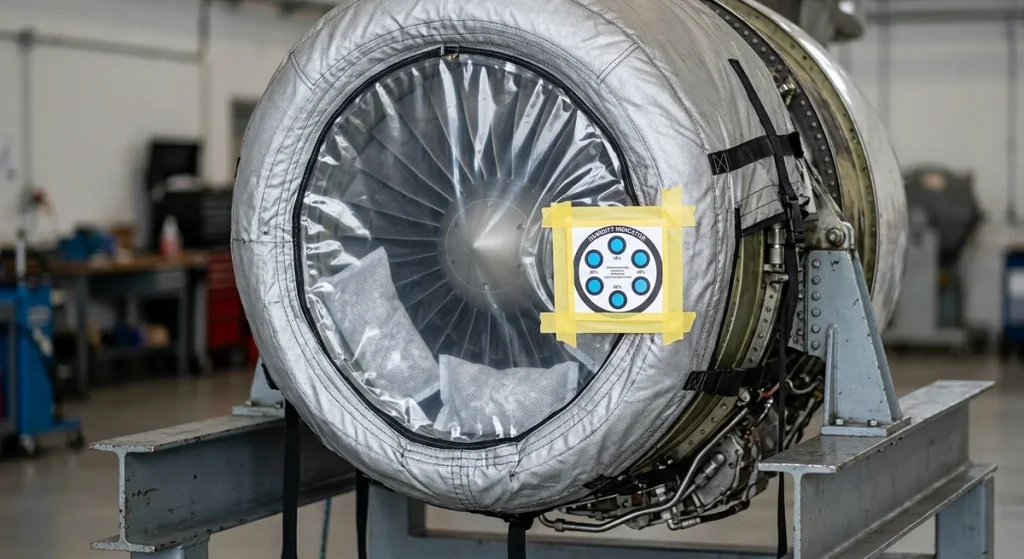
Preservation itself targets corrosion. Depending on transit time and what the manufacturer’s manual prescribes, this ranges from corrosion-inhibiting oil in the fuel and oil systems to full bagging with desiccant and humidity indicators inside the wrap. Sea shipments and engines heading into long-term engine storage get the fullest treatment, because weeks of humid, salty air will corrode an unprotected engine.

Physical protection completes the preparation. Covers close off the inlet, exhaust and any open ports so nothing enters the gas path during handling, and loose accessories are either removed and packed separately or secured against vibration. If the engine ships with its QEC (quick engine change) equipment attached, that configuration goes on the packing list, because it changes both the weight and the handling envelope of the load.

In aircraft engine shipping, everything done at this stage is written down: preservation type, date and the re-preservation interval. The receiving facility needs those records to know what condition the engine is in and when the preservation clock runs out.

Shock and tilt indicator on an engine shipping stand frame

Mounting the engine on an approved shipping stand

The engine travels bolted to a shipping stand: an engine-specific cradle that supports the engine at approved attachment points, sitting on a base frame – in most transport-rated designs through shock mounts that absorb transit loads. Engine manufacturers specify which stands are approved for each model and how the stand must be tied down; using anything else risks case distortion, rejected cargo and warranty arguments. The shipping stand is one of several aircraft engine stand types – our separate guide explains how it differs from storage and maintenance configurations.

Delays at this stage usually come down to the stand itself. A shipment can sit for days because no approved stand is on site, which is why many operators rent one delivered ahead of the move – National Aero Stands provides aircraft engine stands for rent for exactly this scenario. An available stand can still fail the engine: shock mounts age, and degraded isolators protect on paper only. Inspect the stand before the engine goes on it, not after.

The tie-down scheme matters as much as the stand itself. The base frame must be secured to the truck deck, pallet or container floor at the points and angles the stand documentation calls for, with the shock mounts left free to do their work rather than strapped solid. A perfectly good stand lashed the wrong way transmits every pothole straight into the engine.

LEAP-1A stand lead time: National Aero Stands delivers OEM-compliant, shock-mounted LEAP-1A engine stands ahead of the shipment date – book the stand when you book the move.

Crated aircraft engine lowered into an open-top container at a port

Documentation: customs, export control and engine records

In practice, missing paperwork delays engine shipments more often than weather does. An engine crossing a border is a high-value export that customs authorities examine closely, and a missing document can hold the shipment in a bonded warehouse for days while storage fees accumulate. The required documents cover the commercial transaction, the regulatory clearances and the engine’s technical history.

DocumentPurposePrepared by
Commercial or pro-forma invoicedeclares value for customs and dutiesshipper
Packing listdescribes the engine, stand and accessoriesshipper
Air waybill or bill of ladingcontract of carriageforwarder / carrier
Purge certificateconfirms fluids drained or inertedMRO / technicians
Export declarationexport control and trade statisticsshipper / customs broker
Dangerous goods declaration (if applicable)covers any remaining regulated materialsshipper
Engine records: TSN, TSO, logbooks, LLP statusproves history and condition at handoverowner / operator

The technical records matter as much as the customs set. An engine’s value is inseparable from its documented history – time since new, time since overhaul, life-limited part status and back-to-birth traceability. The consignee will check the records package at handover, and gaps discovered on arrival are far harder to fix than gaps caught before departure.

Booking the move through a freight forwarder

Most operators do not book trucks and freighters themselves; a forwarder specialized in aerospace cargo does. The forwarder selects carriers, arranges cranes at both ends, files customs entries, places cargo insurance at the declared engine value and runs a control desk that tracks the shipment around the clock, working within IATA and ICAO rules for air cargo.

Specialization matters. A forwarder who ships engines every week knows which carriers accept engine stands, which airports have the lifting equipment, and how to keep an AOG shipment moving through a weekend customs office. In urgent cases the forwarder also holds options open – a charter on standby, a second routing – while the technical side finishes preparation, so the engine never waits for the paperwork.

Pre-departure checklist

  1. Fluids drained and purge confirmation issued
  2. Preservation completed and recorded, humidity indicators in place
  3. Engine bolted to an approved, serviceable shipping stand
  4. Shock and tilt indicators armed, serial numbers recorded
  5. Customs, export and engine records package complete and copied to the consignee
  6. Carrier booking, insurance and lifting equipment confirmed at both ends
Inspector checking an engine shipping stand after delivery

Shock and tilt indicators: knowing what happened in transit

The shipper loses sight of the cargo the moment the doors close; indicators and data loggers fill that gap. Attached to the stand and the wrap, they record what the engine experienced between departure and arrival, and they are the receiving team’s first source of truth.

DeviceWhat it recordsAction if triggered
Shock indicatorimpact above the g-threshold set in the transport planquarantine the engine, inspect per the manufacturer’s manual
Tilt indicatortipping beyond the allowed anglecheck mounts and oil distribution before acceptance
Humidity indicatormoisture level inside the preservation baggingreplace desiccant, re-preserve, investigate the seal
GPS / data loggerposition, temperature, sometimes vibrationreview route and climate excursions with the forwarder

On arrival, a triggered indicator puts the engine in quarantine until it passes whatever inspection the manufacturer’s manual prescribes for that event – anything from an external check to a borescope inspection.

Receiving the engine: inspection before signature

Handover is where claims are won or lost. Before signing anything, the receiving team inspects the engine externally for transport damage, reads every indicator, checks the stand and tie-downs, and verifies the records package against the packing list. Discrepancies go on the delivery receipt in writing, with photos, before the driver leaves the yard.

Cargo insurance and carrier liability both hinge on what is documented at this moment. A clean receipt signed over a tripped shock indicator can cost the owner the entire claim.

One last task remains if the engine is not going straight onto a wing or into the shop: restart the preservation clock. Confirm the humidity indicators are within limits, log the arrival condition and schedule re-preservation before the interval expires – and assign that task to a named owner in the maintenance system, not to whoever happens to notice the engine in the hangar.

FAQ: aircraft engine shipping questions

What documents are needed to ship an aircraft engine?

A typical set includes a commercial or pro-forma invoice, packing list, air waybill or bill of lading, purge certificate, export declaration and, where applicable, a dangerous goods declaration. The engine records package – TSN, TSO, logbooks and LLP status – travels with the shipment and is verified at handover. What is a purge certificate?

A written confirmation from the shipping facility that the engine’s fuel and oil systems have been drained and pressurized lines purged of flammable vapors. Carriers require it because an engine with residual flammable liquids above the allowed limits falls under dangerous goods rules, and customs authorities may ask for it during clearance on international moves. What happens if a shock indicator is triggered in transit?

The engine is treated as suspect: the receiving team notes the tripped indicator on the delivery receipt, photographs it and holds the engine until it is inspected in line with the manufacturer’s requirements. Depending on the recorded event, that can mean anything from an external inspection to a borescope check. How long does it take to ship an aircraft engine?

Physical transit takes approx. 1-5 days by road, 1-3 days by air freighter on a prepared AOG move (customs and last-mile lifting can stretch door-to-door times beyond that) and 3-8 weeks by sea. Add preparation time on top: preservation, stand mounting and documentation typically need several working days, though AOG shipments compress everything by running the steps in parallel. Do jet engines ship in crates or containers?

The primary protection is the shipping stand, not a box. Some narrow-body engines on low-profile stands fit standard or open-top sea containers, but many stand-and-engine combinations are too wide or tall for a closed container and travel as breakbulk or on flat racks, as do large wide-body engines. Some moves add a crate or full bagging over the stand for weather and handling protection. What does jet engine shipping cost?

There is no flat rate – the total builds up from freight charges, crane lifts at both ends, stand rental, packaging and preservation, insurance at declared value and customs fees. Urgency is the biggest multiplier: a chartered freighter for an AOG engine costs a multiple of a planned road or sea move.

Aircraft Engine Storage: How Long-Term Preservation Works

Long-term aircraft engine storage means protecting an engine against corrosion and moisture damage whenever it will sit idle for more than a few weeks. The process combines preservative oils applied per the engine manufacturer’s manual, desiccants with humidity indicators, sealed bagging and a dedicated storage stand, followed by scheduled inspections until the engine returns to service. Proper preservation protects an asset worth millions of dollars, while a skipped or improvised job can push a parked engine into an early overhaul.

Key takeaways

  • Bare internal steel starts pitting as soon as oil films drain away and humid air gets in – the calendar matters far less than moisture.
  • Storage is tiered: active preservation keeps a short-term engine close to flight-ready, passive preservation seals a long-term engine off from the atmosphere.
  • Good practice keeps relative humidity inside the sealed envelope below approx. 40-50%, verified with color-changing indicators.
  • A stored engine belongs on a purpose-built stand, never on pallets or improvised cradles.
  • The engine manufacturer’s manual is the binding document: it defines fluids, intervals and depreservation steps.

Why idle engines corrode so quickly

While an engine runs, circulating oil keeps a protective film on its bearings, gears, shafts and seals. Once the engine stops turning for good, that film slowly drains away. The gas path was never oil-wetted in the first place – compressor and turbine hardware relies on covers, dry air and desiccant, which is exactly what preservation has to supply. Atmospheric humidity then condenses on internal steel surfaces every time the temperature drops overnight, and each condensation cycle deposits fresh moisture exactly where it does the most harm.

Modern engines make this worse, not better. Tolerances on bearings, fuel metering components and blade roots are tight enough that even minor pitting can put a part outside limits. What looks like light surface rust after a year outdoors can mean rejected hardware at the next shop visit – and on a commercial turbofan, that difference is measured in hundreds of thousands of dollars.

Engine inlet sealed in a barrier bag with humidity indicator card

Short-term vs long-term aircraft engine storage

Preservation effort scales with planned downtime. The industry broadly distinguishes active storage, where the engine is kept close to flight-ready and periodically run or motored, from passive storage, where the engine is fully preserved, sealed and monitored. Exact time thresholds differ between engine types and manufacturers, so the tiers below are typical rather than universal.

Storage tierTypical durationApproachTypical measures
Active (short-term)Up to approx. 30-90 daysEngine kept near flight-readyInlet and exhaust covers, periodic ground runs or dry motoring, visual checks
IntermediateApprox. 90 days to 1 yearPartial preservationPreservative or inhibiting oil in the oil and fuel systems, desiccant at openings, sealed covers
Long-term (passive)Beyond approx. 1 yearFull preservation and isolationComplete fluid preservation, desiccant with humidity indicators, sealed or VCI bagging, storage stand, scheduled inspections

An engine expected back on wing in six weeks does not need full bagging. An engine parked for a lease transition of unknown length should be treated as long-term from day one – re-preserving an engine that was sealed too casually costs far more than the extra bagging would have.

How to preserve an aircraft engine step by step

A preservation sequence starts before shutdown. Where the engine can still be operated, teams run it long enough to bring the oil to full operating temperature, which evaporates accumulated moisture and acidic combustion by-products out of the lubrication system. An engine preserved with contaminated, moisture-laden oil starts its storage life already compromised.

After the final run, the work moves system by system, following the engine manufacturer’s preservation instructions:

  • Oil system: drain and replace with preservative or inhibiting oil where the manual requires it; some modern oils provide adequate short-term protection on their own, which is exactly why the OEM manual, not habit, decides.
  • Fuel system: flush fuel-wetted components with inhibiting fluid so that pumps, controls and nozzles are not left coated in plain fuel residue.
  • Gas path and openings: blank the inlet, exhaust, drains and vents with fitted covers so the core no longer breathes with the weather.
  • External surfaces: treat unpainted metal with corrosion-preventive compound (CPC) and cap exposed probes, drains and mounting flanges.

What follows is monitoring rather than maintenance: desiccant holds the sealed atmosphere dry, and indicator readings logged at each check prove that it stayed that way.

Hygrometer and thermometer in an engine storage facility

Desiccant, humidity indicators and VCI bagging

Sealing an engine traps a volume of air inside, and that air carries moisture. Desiccant – typically silica gel in bags or dehydrator plugs – absorbs it. Classic indicating gel is deep blue when dry and turns pink as it saturates; many current indicators use orange-to-green chemistry instead, but the principle is the same: a color you can read at a glance without breaking the seal. Humidity indicator cards mounted behind windows in the bagging do the same job for the whole envelope.

For genuinely long-term storage, many operators go one step further and bag the entire engine in barrier film, often with volatile corrosion inhibitor (VCI) material that releases a vapor which passivates metal surfaces inside the sealed volume. Exact thresholds vary by preservation scheme, but most programs converge on keeping the environment around and inside the engine below approx. 40-50% relative humidity – dry enough that corrosion chemistry effectively stalls.

MethodWhat it doesWhere it is used
Desiccant (silica gel bags, dehydrator plugs)Absorbs moisture trapped inside the sealed envelopeEngine openings, inside bagging
Humidity indicators (cards, indicating plugs)Visual moisture check without breaking sealsBag windows, dehydrator plugs
VCI film or baggingReleases corrosion-inhibiting vapor around metal surfacesLong-term sealed storage
Preservative and inhibiting oilsLeaves a protective film on internal wetted surfacesOil system, fuel system, cylinders
Controlled storage environmentKeeps ambient humidity low and temperature stableIndoor, off-ground warehouse storage
Technician inspecting an engine storage stand frame

Store the engine on a proper stand

Where the engine physically sits during storage is as important as how it is sealed. A purpose-built engine stand supports the engine at the mount points approved by the manufacturer and keeps it clear of floor moisture. Just as important over a long storage period, the engine can be inspected, relocated or loaded for shipment without re-rigging the cradle. Stands with shock-absorbing cradles also protect bearings from vibration when a stored engine does have to be relocated. Pallets, improvised cradles or resting an engine on its cowling risk structural damage that no amount of desiccant will fix. Our overview of aircraft engine stand types explains how storage stands differ from transport and maintenance configurations.

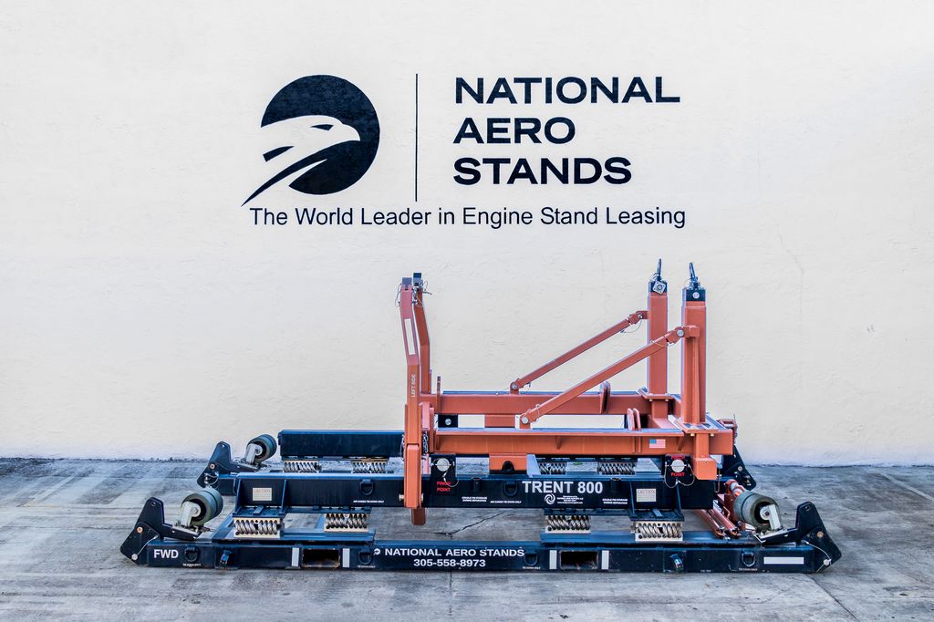
Need a Trent 800 engine stand for storage or shipping? The Trent 800 engine stand is available for rent and lease from National Aero Stands.

Because storage periods are often open-ended, renting a stand is common practice: it avoids tying up capital in hardware that may sit under an engine for years. National Aero Stands keeps engine stands for CFM56, LEAP, Trent, GE90 and PW engine families available for exactly this scenario.

Piston engine storage: how the process differs for GA aircraft

General aviation piston engines follow the same logic with different mechanics, and the practices are documented in the FAA’s Aviation Maintenance Technician Handbook – Powerplant. The final ground run should bring oil temperature into the normal operating range – approx. 180-220°F for most types – and hold it there long enough to drive off moisture and acids; how long that takes is set by the engine maker’s service guidance, not by a universal clock. Crews then remove the spark plugs and spray CPC directly into the combustion chambers while rotating the engine, coating cylinder walls before the bores are sealed. Dehydrator plugs with indicating silica gel screw into the spark plug bores, and moisture-proof tape and cowl plugs seal the exhaust, breather and carburetor intake.

Where the aircraft is parked matters too: standing over grass or bare dirt raises local humidity and measurably accelerates corrosion compared to pavement or hangar floor.

A few practices to avoid, because they cause real damage:

  • Do not store components submerged in diesel or similar fluids – it degrades seals and elastomers.
  • Do not rotate the propeller backward; it can damage dry vacuum pump vanes and bleed oil out of hydraulic lifters.
  • Never hand-rotate the engine without confirming magnetos are off and grounded.
  • Never attempt the first post-storage start without checking for liquid lock – pooled oil in a lower cylinder can bend connecting rods instantly.
PW1100G engine stand from the National Aero Stands fleet
PW1100G engine stand from our fleet – specs and availability

How often should a stored engine be inspected?

The inspection interval depends mainly on the storage environment. In a dry, arid climate, a documented visual check of seals, covers and indicators approx. every 90 days may be adequate. In humid coastal environments, dehydrator plugs and indicator cards deserve attention weekly, because desiccant saturates far faster and a color change is the only early warning you get.

Every check should be logged: which indicators were read, which desiccant was replaced, what the ambient conditions were. For leased or stored assets awaiting sale, that paper trail is part of the engine’s value – a buyer or lessee will ask how the engine was kept, and records are the only credible answer.

Returning a stored engine to service

Depreservation deserves the same discipline as preservation. Rushing it risks foreign object damage and mechanical harm from residual preservation materials. A typical return-to-service sequence looks like this:

  1. Remove all covers, plugs, desiccant and indicator devices – and account for every single item to rule out foreign objects left in the gas path.
  2. Inspect per the OEM depreservation instructions, including borescope checks where called for.
  3. Drain preservative fluids and service the engine with operational oil and fuel.
  4. Rotate by hand or motor the engine to confirm free rotation; on piston engines, verify there is no hydraulic lock before the first start.
  5. Perform the ground runs the manual requires, flushing residual preservation compounds and checking for leaks.
  6. Record the depreservation in the engine records, closing the loop that began at the final run before storage.

If the engine is headed to a shop visit rather than back onto the wing, it will travel on the same stand it was stored on – our guide to jet engine transportation covers what that move involves. If the engine crosses a border on the way, the aircraft engine shipping process – purge confirmation, customs paperwork, shock indicators – comes on top.

Standards, manuals and documentation

There is no single universal storage regulation. The binding requirements come from the engine manufacturer’s manuals – the preservation and storage chapters of the engine maintenance manual and the related instructions for continued airworthiness. On commercial engines the work is typically carried out or overseen by repair stations certificated under 14 CFR Part 145 or the EASA equivalent, and 14 CFR Part 43 governs who may perform and sign for the tasks. Military operators apply their own long-term packaging and preservation specifications, and lessors add return conditions on top. A stored engine that comes with complete preservation records sails through redelivery; one without them gets opened up, borescoped and argued over.

FAQ: aircraft engine storage

How long can an aircraft engine sit without preservation?

Not long. Once regular operation stops, oil films drain and corrosion can begin within weeks, faster in humid climates. Depending on the manufacturer, the first preservation steps can be required after as little as approx. 7 days of expected inactivity, with fuller preservation at approx. 30 and 90 day thresholds. The engine’s own manual defines the exact limits. What humidity level is recommended for engine storage?

Most preservation schemes target below approx. 40-50% relative humidity inside the sealed envelope and in the storage area, because corrosion chemistry slows dramatically in dry air. In practice crews manage to the indicators: when a card or plug shows the envelope creeping toward the limit, the desiccant is replaced rather than left to saturate. Do stored engines need to be run periodically?

Only in active, short-term storage, where periodic ground runs or dry motoring keep oil distributed and the engine flight-ready. In passive long-term storage the engine is not run at all; protection comes from preservative fluids, desiccant and sealing, verified through scheduled visual inspections instead. Can an engine be stored on its transport stand?

Yes, and it usually should be. A purpose-built stand supports the engine at OEM-approved mount points, keeps it off the floor and away from ground moisture, and lets the engine be moved or shipped without re-rigging. Many operators rent a stand for the full storage period. What does jet engine storage cost?

There is no standard figure – cost depends on warehouse space and climate control, preservation labor and materials, stand rental, insurance and periodic inspections. Passive long-term storage costs more to set up but little to maintain; active storage is cheaper up front but consumes labor continuously. What is VCI packaging?

VCI stands for volatile corrosion inhibitor. VCI film or bagging slowly releases a vapor that settles on metal surfaces inside a sealed volume and interrupts the corrosion reaction. Combined with desiccant and humidity indicators, it is a standard element of long-term engine bagging.

Military Aircraft Ground Support Equipment: Types, Roles and Mission Readiness

Military aircraft ground support equipment (GSE) covers the tow tractors, ground power units, munitions loaders, maintenance stands and test systems that keep defense aircraft mission-ready between flights. It does the same core jobs as civilian GSE – moving, powering and servicing aircraft – but is engineered for unimproved surfaces, climate extremes and deployment far from fixed infrastructure. Take away the 400 Hz power cart or the bomb lift truck, and a deployed squadron stops flying within days.

Key takeaways

  • Military GSE spans six broad categories: towing, power and start, munitions handling, servicing vehicles, access and maintenance stands, and test systems.
  • The main difference from civilian GSE is ruggedization: reinforced construction, all-terrain mobility and the ability to deploy by airlift to austere bases.
  • Armament loading equipment – bomb lift trucks and linkless ammunition loading systems – has no civilian equivalent.
  • Matching ground power correctly (115/200V 400 Hz AC, 28V DC and on some fighters 270V DC) protects avionics during servicing.
  • With preventive care, core GSE typically serves 15 to 20 years.

What is military aircraft GSE?

Ground support equipment (GSE) is the machinery that services an aircraft between flights – everything a parked airplane or helicopter needs at a gate, in a hangar or on a remote stand. These systems support the maintenance, servicing and turnaround tasks that keep an aircraft ready for flight; airworthiness itself comes from work performed to approved data, not from the equipment alone. For the civilian baseline – what airlines and EASA Part-145 maintenance organizations use every day – see our full guide to aviation ground support equipment.

In the defense sector, military aircraft ground support equipment underpins every ground-based activity. It keeps fleets mission-ready and lets them launch from virtually any location in the world, from a permanent airbase with fixed hangar infrastructure to a forward operating base with an unimproved surface and no local supply chain.

The scope is wider than on the airline side. Ground crews rely on vehicles, power systems, access platforms and support units to move and maintain aircraft on the tarmac – and, on top of that, defense operations need dedicated machinery to load bombs, missiles, torpedoes and heavy munitions.

Rugged military-spec ground power cart in olive drab

Military vs civilian GSE: what actually changes

Most equipment categories exist on both sides. What changes is the design envelope. Military GSE is engineered for harsher environments, higher duty cycles and deployability – the ability to be flown or shipped to wherever the aircraft go and work reliably on arrival. Much of it is also built to referenced military standards for environmental resistance (the MIL-STD family, with MIL-STD-810 environmental testing being the most commonly cited example), rather than to the airline-side equipment standards maintained by bodies such as the SAE AGE committee.

AspectCivilian / airline GSEMilitary GSE
Operating surfacePaved ramps and apronsPaved bases plus unimproved, uneven or temporary surfaces
Design referencesAirline and airport specs, manufacturer requirements, IATA/ICAO guidanceMilitary environmental and transportability standards (MIL-STD family)
DeployabilityStays at one airport or stationSized and ruggedized for transport by airlift, sea or road; light units fit tactical airlifters, the heaviest move by strategic airlift
Power and cooling demandSized to airliner electrical and air conditioning loads – large types draw 90 kVA or moreMatched per airframe: transports and tankers approach airliner loads, fighters draw less but need specific connectors and DC profiles
Unique categoriesCatering, passenger boardingArmament loaders, ammunition loading systems, weapons transport trailers
Duty profileScheduled operations, predictable tempoSurge operations, continuous sortie generation, extreme climates

Thicker frames, sealed electronics, all-terrain running gear and heavy-duty drivetrains carry a real cost in weight and price – they are bought so a ground crew can keep servicing aircraft when the ramp is gravel and the forecast is sand.

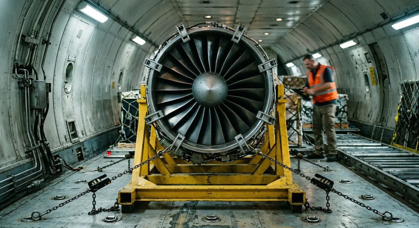
Palletized ground support equipment inside a military transport aircraft

Main types of military aircraft ground support equipment

A well-equipped airbase deploys several distinct categories of machinery to cover different roles. The right mix depends on the aircraft types on station, the required towing and power capacity, available space and the operating environment.

CategoryWhat it doesTypical examples
Towing and pushbackMoves aircraft on the ramp and into hangars without running enginesHeavy tow tractors, pushback tugs, remotely controlled electric tugs
Power and start systemsSupplies electricity and pressurized air with engines shut downGround power units (GPUs), air start units
Munitions handlingLoads and transports weapons and ammunitionBomb lift trucks (“jammers”), linkless ammunition loading systems, weapons trailers
Servicing and logistics vehiclesDelivers fluids, cargo and personnel to the aircraftFuel trucks, water trucks, air conditioning and heating carts, cargo deck loaders, mobile maintenance units
Access and maintenance standsGives technicians stable, safe access to the airframe and enginesMaintenance platforms, B-stands, engine stands and transport bases
Test and diagnostic systemsVerifies aircraft systems on the ground before flightHydraulic test stands, cabin pressurization and leakage testers

Ground power units and voltage needs

Ground power units supply electrical power to aircraft when the main engines are shut down. External power lets crews run onboard systems, complete pre-flight diagnostics and hold aircraft at readiness without draining internal batteries. Because defense fleets operate many different airframes, matching the correct power profile to each aircraft’s electrical architecture is a routine but safety-critical task.

Power profileTypical usersNotes
115/200V AC, 400 Hz, three-phaseStandard AC bus on transports, tankers, fighters and most fixed-wing typesOutput sized to the airframe – from tens of kVA for a fighter to 90 kVA or more for a large transport; fixed solid-state units are common in hangars
28V DCCarried alongside the AC bus on most airframes; primary power on many helicoptersServicing and system checks often need both AC and DC connections, not one instead of the other
270V DCSome fifth-generation fightersSupplied by dedicated or multi-output ground power units
Battery-powered GPUsGrowing across fleet typesDeliver the same power profiles with low noise and no flight line exhaust

Feeding the wrong profile into an airframe can damage avionics and mission systems worth more than the entire GPU fleet, so flight lines document the required power profile per aircraft type and verify it before every hookup.

Munitions loaders and ammunition systems

Ground crews cannot manually lift large weapons, so mechanized loaders are a fixture of daily flight line work. Armorers use bomb lift trucks – known on the flight line as “jammers” – to hoist bombs, external fuel tanks and large pods, then align them precisely with wing pylons or internal bay attachment points.

On aircraft with internal rotary cannons and linkless gun systems, armorers use dedicated ammunition loading equipment to transfer rounds into the onboard drum; depending on the installation, the same equipment also downloads spent cases and unfired rounds. Mechanizing the transfer speeds up arming considerably and keeps personnel clear of explosive hazards. At the logistics scale, high-capacity cargo deck loaders raise palletized munitions and supplies straight into transport aircraft, and how smoothly that chain runs directly affects how fast a squadron can arm and launch.

Access platforms and engine stands

Maintenance stands and raised access platforms complete the standard flight line setup. They give technicians a stable workspace for inspections and repairs on tall airframes – upper fuselage, tail surfaces, engine pylons – where ladders would be slow and unsafe. Engine changes add one more requirement: a transport-rated engine stand that holds the removed engine safely on the ground and on the road. For tankers, transports and patrol aircraft powered by civil-derived turbofans – a P-8’s CFM56 or a KC-135R’s F108 is an airline engine under a military designation – that part of the toolset overlaps directly with the airline world. Combat engines such as the F100 or F135 have different mounts and dimensions and ride on their own dedicated stands. The moves themselves – by road, air or sea – follow the practices described in our aircraft engine transportation guide.

Need an aircraft engine stand? National Aero Stands rents and leases transport-rated stands for CFM56, LEAP, GE90, Trent and PW engine families – browse available engine stands.

Fighter jet engine on a maintenance trailer in an engine shop

Hydraulic and pressurization test systems

Fluid and air systems are checked on the ground during maintenance and troubleshooting, without starting the engines. Where the aircraft design and maintenance procedures allow, hydraulic test stands supply pressurized fluid so technicians can actuate landing gear, flight control surfaces and weapon bay doors, monitoring return flow to catch internal bypasses or external leaks before they compromise handling.

On pressurized aircraft, cabin pressurization and leakage testers do the equivalent job for the pressure vessel: they force air into the fuselage and measure the pressure decay rate to pinpoint degraded door seals or valve malfunctions. Electric motor driven units of this class are sized to pressurize even a large transport aircraft quickly. A seal found leaking at the stand costs a part and a technician’s hour; the same fault at altitude costs an aborted mission and an unscheduled repair.

Expeditionary shelter hangar with maintenance stands around a helicopter

Maintenance and service life of military GSE

An unserviceable power cart can hold a jet on the ground as surely as a missing spare part, so the GSE fleet gets its own maintenance program. With proper preventive care, a service life of approx. 15 to 20 years from core machinery is a common planning figure in defense GSE lifecycle guidance. Reaching that lifespan takes routine physical inspection plus condition monitoring: modern support units carry sensors and telematics that track performance metrics, fuel consumption, battery health and active faults in real time, so crews can fix minor issues before they become breakdowns that ground aircraft.

On the hardware side, manufacturers increasingly build modular designs into ground units so field crews can swap faulty components quickly, and MRO providers extend equipment life well beyond the initial warranty period through scheduled overhaul. The same discipline applies to spare engines held in reserve – correct aircraft engine storage keeps a war-reserve powerplant ready for installation instead of quietly corroding.

Current trends: electric and autonomous GSE

Electrification is the change furthest along: electric and hybrid GSE removes exhaust from the area around sensitive turbine intakes, cuts noise for ground crews and reduces fuel logistics on base. Current lithium-ion packs let many equipment types cover a substantial part of a shift, depending on duty cycle and charging support – the heaviest units still test that limit.

Autonomy is the second shift: tow tractors and cargo loaders fitted with spatial sensors can follow programmed paths across a crowded ramp without a driver, which frees skilled personnel for technical work and reduces the risk of vehicle-to-aircraft collisions – one of the most expensive and most avoidable categories of ground damage.

Choosing and sourcing military GSE

Procurement teams weigh a short list of parameters before fielding new units:

  1. Capacity and specifications – power output and towing capability must match aircraft weight and electrical demand to avoid component damage.
  2. Operating environment – all-terrain capability and climate tolerance decide whether a unit works at a forward operating base or only at home station.
  3. Commonality – equipment that serves multiple airframes saves enormous logistical effort; sourcing a unique tool for every aircraft type multiplies the supply chain.
  4. Footprint – crowded flight lines and confined storage dictate maximum physical dimensions.

The new-vs-used question follows the same logic as elsewhere in aviation. Factory-fresh orders carry long lead times; the used aircraft ground support equipment market can deliver quickly during surge demand, provided each asset passes a thorough technical inspection covering original specifications, current wear and service history. Balancing new orders with well-maintained secondary-market units – and mixing standardized platforms with the few customized ones a fleet genuinely needs – is what builds a cost-effective ground network for any airbase.

Whichever route a force takes, the buying criteria stay the ones above: capacity matched to the airframes on station, tolerance for the operating environment, commonality across types and a footprint the ramp can absorb. Get those four right and the ground fleet stops being the limiting factor in sortie generation.

FAQ: military aircraft ground support equipment

What counts as ground support equipment in military aviation?

Ground support equipment (GSE) is the collective term for machinery used to service aircraft on the ground between flights: tow tractors, ground power units, air start units, loaders, maintenance stands and test systems. It covers everything an aircraft needs while parked – power, movement, access, servicing and diagnostics – without running its own engines. What are the main types of military ground support equipment?

The main GSE types fall into six groups: towing and pushback vehicles, power and start systems, servicing and logistics vehicles, access and maintenance stands, test and diagnostic systems, and – in military aviation only – munitions handling equipment such as bomb lift trucks and ammunition loading systems. How is military GSE different from civilian GSE?

Military GSE is ruggedized: reinforced frames, all-terrain mobility, higher power output and construction referenced to military environmental standards rather than airline specs. It is also designed for deployability – transport by airlift to austere bases – and includes armament loading categories that have no civilian counterpart. What is a “jammer” in military aviation?

A jammer is the flight line nickname for a bomb lift truck – a compact hydraulic vehicle armorers use to hoist bombs, missiles, fuel tanks and pods, then align them precisely with an aircraft’s wing pylons or internal bay attachment points. It replaces manual lifting for loads far too heavy and hazardous for crews to handle. Why do military aircraft need 400 Hz ground power?

400 Hz is not a military peculiarity – airliners use it too, because the higher frequency keeps onboard generators and motors small and light. The standard interface is 115/200V three-phase AC at 400 Hz, and ground power must match that profile to run avionics safely with engines off. Most airframes also carry a 28V DC bus, helicopters are often DC-primary, and some fifth-generation fighters add 270V DC – which is why bases operate several GPU profiles. How long does ground support equipment last?

With routine inspection and preventive maintenance, core ground support equipment typically serves approx. 15 to 20 years. Condition monitoring via sensors and telematics, modular component design and periodic MRO overhauls are the main factors that push equipment toward the upper end of that range.

Jet Engine Transportation: How Engines Move by Road, Air and Sea

Jet engine transportation relies on three main methods: road haulage on an air-ride trailer, air freight aboard a cargo aircraft, and sea freight for long moves that are not time-critical. Size, distance and deadline decide between them – a narrow-body engine of approx. 2.3-3.1 t travels well by truck, while a wide-body engine of approx. 4.5-8.5 t may need a 747 freighter, a ship or, at the largest fan diameters, an AN-124. In every case, the engine rides on a manufacturer-approved transport stand that isolates it from shock and vibration.

Key takeaways

  • An air-ride trailer covers most engine moves. Freighters take over when an AOG clock runs or an ocean is in the way; sea freight suits planned repositioning measured in weeks.
  • OEM documents name the approved transport stand, the tie-down scheme and the shock limits for every engine model – shipping on anything else invites warranty and lease-return disputes.
  • Engine size decides more than distance does. A complete GE90-115B on its stand generally does not pass through a 747 freighter side door – it flies with the fan case removed, goes on an AN-124 or moves by road and sea.
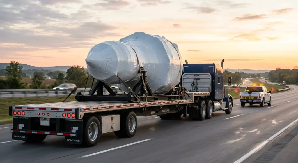
Aircraft engine on an air-ride flatbed trailer at dawn

Why moving a jet engine is a specialist job

A jet engine weighs as much as a small truck, but it tolerates none of a truck’s handling. One hard jolt can damage fan blades, bearings or the accessory gearbox, and the manufacturer’s shock limits apply from the moment the engine leaves the pylon. Replacement values for commercial engines run into the millions of dollars, and into the tens of millions for the largest wide-body types, so a transport error is never a minor claim.

Time pressure makes it harder. When an aircraft is grounded (AOG), lost revenue and rebooking costs accumulate by the hour – for a wide-body operation, industry estimates run to tens of thousands of dollars per hour. That is why a replacement engine often has to move from an MRO shop to a stranded aircraft on another continent within days, not weeks, and why safe aircraft engine transportation is a logistics discipline of its own rather than ordinary heavy freight.

Planning starts from two numbers, engine weight and fan diameter, because together they set the trailer, the crane capacity and the freighter door the move has to clear. The table below shows the most common engine families – bare engine weight, before adding a transport stand that can weigh another 1-3 t.

EngineTypical aircraftApprox. dry weightApprox. fan diameter
CFM56-7BBoeing 737NGapprox. 2.4 tapprox. 1.55 m
LEAP-1AAirbus A320neoapprox. 3.0 tapprox. 1.98 m
Trent 700Airbus A330approx. 4.8 tapprox. 2.47 m
Trent 800Boeing 777 (early)approx. 5.9-6.1 tapprox. 2.79 m
GE90-115BBoeing 777-300ERapprox. 8.3 tapprox. 3.25 m

One mode is missing from the list of options on purpose: rail. Coupling impacts and track-induced vibration can exceed the shock limits engine manufacturers set for their products, so the industry keeps engines on air-suspended trucks, freighters and ships.

The three main jet engine transportation methods

Real shipments are rarely single-mode: even a 747F charter begins and ends with a truck leg, and a sea move adds port handling on both sides. The table compares the three methods on time, cost and their main constraint.

MethodBest forTypical transit timeRelative costMain constraint
Road (air-ride trailer)domestic and regional moves, airport and port legs1-5 daysbaselineoversize permits for wide-body engines
Air freighterAOG response, intercontinental urgency1-3 days door to doorhighest – a multiple of roaddoor dimensions, freighter availability
Sea freightplanned, non-urgent intercontinental moves3-8 weekslow to moderatetransit time, humidity, preservation effort
Engine on a wheeled transport stand loaded toward a freighter nose door

Road transport: the default for most engine moves

For domestic and regional distances, a dedicated truck with an air-ride trailer is the standard answer. Air suspension replaces steel springs with pressurized air bags, smoothing out road shock before it reaches the cargo. The transport stand is secured to the trailer deck at multiple points, and a fitted transport cover protects the inlet and exhaust from weather and debris.

A CFM56-7B, with its 1.55 m fan, usually stays within normal trailer dimensions and needs no special permits. A LEAP-1A at approx. 1.98 m is a borderline case: once it sits on a stand, the loaded width can cross oversize thresholds in some jurisdictions. Wide-body engines cross them almost by definition – with fan diameters of 2.5-3.25 m, a Trent or GE90 becomes an oversize load, which brings route surveys, escort vehicles and permit lead times into the plan.

The single most useful road routine is the tie-down check after the first kilometers: shock mounts settle under load, and straps that were tight at the dock work loose. Drivers briefed on high-value aerospace cargo repeat that check at every stop and slow down over rough sections. Loading itself is done by crane or heavy forklift, lifting the engine together with its stand – never by slinging the bare engine outside approved lifting points.

IAE V2500 engine transportation stand with cradle and shock mounts
IAE V2500 transport stand from our fleet – specs and availability

Air freight: freighters for urgent and wide-body moves

When an AOG clock is running or an ocean is in the way, engines fly. Narrow-body engines travel on main-deck positions of standard freighters. Wide-body engines almost always need a dedicated freighter – typically a 747F loaded through the side cargo door, or an AN-124 from Antonov for the largest packages.

The limit is usually the package envelope, not the mass. Boeing rates the 747-8 Freighter for well over 100 t of payload, so no engine’s weight troubles the airframe; the question is whether the engine on its stand passes through the side door. That is why the largest types – the GE90-115B that powers the 777-300ER, or the big Rolls-Royce engines like the one covered in our Trent 800 overview – need extra planning.

EngineApprox. fan diameterStandard 747F loadingCommon air freight solution
CFM56-7Bapprox. 1.55 mfitsmain deck of a standard freighter
LEAP-1Aapprox. 1.98 mfitsmain deck of a standard freighter
Trent 700approx. 2.47 mfits with planning747F side cargo door
GE90-115Bapprox. 3.25 mgenerally does not fitAN-124, or surface transport; fan case may be removed and shipped separately

Per kilometer, nothing costs more than dedicated air freight. Against a wide-body AOG bill it still tends to win, although not every grounded aircraft justifies a charter – a narrow-body engine often rides a scheduled freighter on a next-flight-out booking at a fraction of charter cost.

Sea freight: the slow, economical option

For planned moves with no deadline – engines heading to long-term parking, cores returning after a sale, or spare engines positioned in advance – sea freight costs a fraction of a charter flight. Most engines on transport stands are too wide or too tall for a standard closed container, whose internal width is approx. 2.35 m, so they travel as breakbulk, on flat racks or in open-top containers; only some narrow-body engines on low-profile stands fit inside a standard box.

The price of the low rate is time and environment. Door-to-door times of several weeks are normal, and marine air is humid and salty, so the engine must be sealed, bagged and protected with desiccant before the voyage. The preservation requirements overlap heavily with those for aircraft engine storage, and an engine arriving after a long voyage should be treated much like one coming out of storage: inspect it, read the humidity indicators, re-preserve if needed.
Technicians preparing a wrapped engine on a transport stand in an MRO hangar

Transport stands: the equipment that carries the engine

After removal from the pylon the engine is lowered into a transport stand – a two-part assembly made of an engine-specific cradle and a wheeled or skid-mounted base frame. The cradle supports the engine at interface points the OEM defines for that stand and engine model, usually based on the engine’s approved handling and mount locations, so transit loads pass through structure designed to carry them rather than through the casings. Aircraft engine transportation stands are the single most model-specific piece of equipment in the whole chain – our guide to aircraft engine stand types covers how transport cradles differ from storage and maintenance configurations.

Between cradle and base sit shock mounts – elastomer isolators that absorb vibration and impact energy before it reaches the engine. This is what separates a transport-rated stand from a simple shop fixture: the first is designed for the road, the second is not, and confusing the two is one of the most expensive mistakes in engine logistics.

Engine manufacturers define which stands are approved for their products, including permitted transport modes, tie-down schemes and shock limits. Using a non-approved stand can void warranty coverage and can distort an engine case in ways that only show up at the next shop visit. A wide-body engine needs a stand built for its mass and geometry – see the Trent 700 engine stand for a shock-mounted transport configuration for the A330 fleet, or the GE90 engine stand at the top end of the scale. When no approved stand is on site, renting is standard practice: National Aero Stands offers aircraft engine stands for rent and lease across the major engine families.

Need a CFM56-7B engine stand? National Aero Stands rents and leases shock-mounted, OEM-compliant CFM56-7B engine stands ready for road and air transport – available on AOG timelines.

How to choose the method: size, distance, deadline

Three constraints filter the options quickly. A fan diameter above approx. 3 m rules out most freighter side doors. An ocean rules out road alone. An AOG deadline rules out the sea. Whatever passes all three filters is then a question of budget – planned moves open the cheaper road and sea routes, urgency forces air.

Road sets the cost baseline in jet engine transportation. Sea freight can undercut it on long routes, at the price of tying the asset up for weeks; a dedicated freighter costs a multiple of either. Cranes at both ends, permits, insurance and stand logistics add to every option, so price the move door to door, not leg by leg.

Choosing the method settles less than it seems. The engine still has to be preserved, mounted, cleared through customs and monitored in transit, and a missing purge certificate stops a charter as surely as a missing crane. We cover that side step by step in our guide to the aircraft engine shipping process.

FAQ: common questions about jet engine transport

How much does a jet engine weigh?

Narrow-body engines weigh approx. 2.3-3.1 t: a CFM56-7B is approx. 2.4 t and a LEAP-1A approx. 3.0 t. Wide-body engines run approx. 4.5-8.5 t: a Trent 700 is approx. 4.8 t dry and the GE90-115B tops the scale at approx. 8.3 t. Add roughly 1-3 t for the transport stand when planning cranes and trailers. Can a jet engine be transported by rail?

Rail is generally avoided for commercial jet engines: coupling impacts and track vibration can exceed OEM shock limits even on a shock-mounted stand, and approvals and handling interfaces for rail barely exist in engine logistics. The standard surface solution is a dedicated truck with an air-ride trailer, which keeps recorded shock loads far lower and allows door-to-door delivery. What is an air-ride trailer?

An air-ride trailer replaces steel-spring suspension with pressurized air bags that absorb road shock and vibration. Combined with the shock mounts built into the transport stand, it keeps impact loads on the engine within manufacturer limits. It is the default equipment for road moves of commercial aircraft engines. Why can’t the largest engines fly in a 747 freighter?

Because of diameter, not weight. GE Aerospace quotes a fan diameter of approx. 3.25 m for the GE90-115B, and on its stand the package is too large for standard 747F doors. Operators charter an AN-124, remove the fan case for separate shipment, or move the engine by road and sea instead. Who decides which transport stand may be used?

The engine manufacturer. OEM documentation defines approved stand types, tie-down schemes, transport modes and shock limits for each engine model. Operators and lessors also require records showing the engine traveled on an approved, serviceable stand – an unapproved stand can void warranty and complicate lease returns. How fast can an engine cross continents in an AOG case?

With a freighter charter and prepared paperwork, an engine can move between continents in approx. 1-3 days door to door: a road leg to the airport, the flight, customs clearance and final delivery. The usual bottlenecks are freighter availability and customs, not the flying time itself.

Aircraft Engine Test Stand: How Jet Engines Are Tested on the Ground

An aircraft engine test stand is a ground facility that runs a complete gas turbine engine under its own power while instruments record thrust, temperatures, spool speeds, fuel flow and vibration. Usually called a test cell or test bed, it is where new and freshly overhauled engines prove they meet specification before anyone clears them for flight. It is a different tool from the transport and maintenance stands that carry engines around a shop – two product categories that share a name and almost nothing else.

What is an aircraft engine test stand?

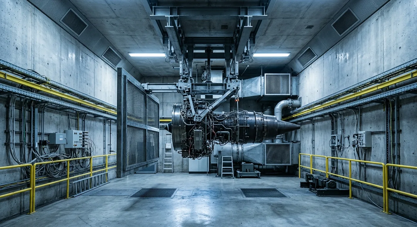
In a test cell, a complete gas turbine engine is rigged to a thrust frame, started under its own power and taken through its full power range while a sensor network records how it behaves. Engine manufacturers use development test cells to characterize and certify new designs. MRO shops use production test cells to confirm that an engine coming out of overhaul delivers rated thrust, stays inside its temperature limits and shows no abnormal vibration before anyone bolts it back onto a wing.

Flight testing alone cannot do this job – discovering a severe vibration problem at 30,000 feet is an unacceptable risk. Development programs do push engines to their limits on the ground, but an acceptance run after a shop visit is a different exercise: a defined test schedule from the engine maker’s manual, with limits to meet at each step rather than limits to find. In both cases the cell isolates the variables: airflow, fuel temperature, ambient conditions and applied load are all measured or controlled, so every anomaly can be traced to its source.

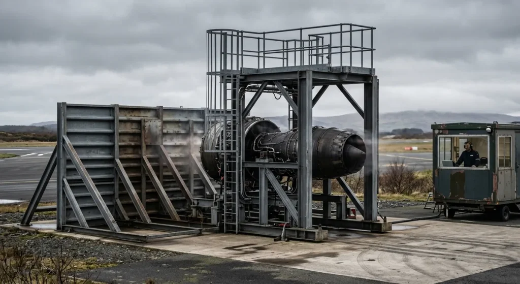
Two basic layouts exist. Indoor test cells enclose the engine in a hardened chamber with a tuned air inlet and an augmenter exhaust tube, which contains the noise and allows testing in any weather. Outdoor test stands mount the engine on an open thrust frame – simpler and cheaper to build, but hostage to wind and ambient conditions.

Test cell control room with observation window

Test cell vs transport stand: two different tools

The terminology causes real confusion, because “engine stand” covers two entirely different product categories. A test stand runs a live engine and measures its performance. A support stand – transport, shipping, storage or maintenance – holds a non-running engine safely during logistics and shop work, and it never sees an engine start. Buyers searching for one frequently land on the other, so the table below puts the two side by side.

FeatureEngine test stand (test cell / test bed)Engine support stand (transport / maintenance)
PurposeRun the engine and measure performanceHold, move, store or service a non-running engine
Engine stateOperating, up to full takeoff powerShut down, often preserved for storage
Key hardwareThrust frame, load cells, data acquisition, fuel and air conditioningCradle, base frame, shock mounts, casters, tie-down points
Typical locationDedicated facility at an OEM or engine shopHangar floor, truck bed, freighter deck, warehouse
Cost scaleMulti-million dollar installationA fraction of that; commonly rented per project

If what you actually need is hardware to ship, store or work on an engine, start with our overview of the types of aircraft engine stands used in maintenance and transport – it covers cradles, shock mounts, load ratings and model compatibility. Support stands themselves are one category of aviation ground support equipment – the wider machinery that services aircraft between flights.

Need a CFM56-7B engine stand for shipping or shop handling? National Aero Stands has OEM-compliant stands ready for dispatch.

Engine on a transport stand in a hangar with a test cell building beyond

Core components of a jet engine test cell

A turbofan or turbojet cell is built around a small set of load-bearing and measurement systems working together:

  • Thrust frame and mounting adapters – anchor the engine during high-thrust operation and prevent dangerous structural shifts.
  • Calibrated load cells – convert the longitudinal force absorbed by the thrust frame into a precise thrust reading.
  • Inlet section with debris screens – delivers smooth, measured airflow to the fan face and protects against foreign object damage.
  • Augmenter tube and exhaust silencing – carry the exhaust stream out of the cell and suppress noise to permitted levels.
  • Data acquisition system – hundreds of channels of pressure, temperature, speed and vibration data feeding a shielded control room.

Turboshaft and turboprop rigs add a second family of hardware, because their output is shaft power rather than pure thrust: dynamometers and torque meters apply and measure rotational load, while gearboxes, inertia flywheels and interconnecting drive shafts link the engine to the measurement train. Multi-faceplate mounting walls let one firewall accept several engine models, which cuts changeover time between test campaigns, and portable test stand builds bring a reduced diagnostic suite directly to the flight line instead of trucking the engine to a stationary laboratory.

What is measured during an engine test run?

A modern acceptance run records every parameter that defines engine health, and the operator compares each reading against limits set by the engine manufacturer. Whether a given engine needs that run at all depends on the work scope: the manufacturer’s approved maintenance data, applied under 14 CFR Part 43, defines which shop visits end in the cell and which do not.

Parameter groupWhat is recordedWhy it matters
ThrustForce at the thrust frame load cellsConfirms the engine delivers rated takeoff and climb thrust
Spool speeds (N1 / N2)Fan and core rotation speedsVerifies compressor stages stay within structural margins
EGT (exhaust gas temperature)Turbine exhaust heat and EGT marginReveals combustion anomalies and remaining time on wing
Fuel flowConsumption across the power rangeCombined with measured thrust, yields specific fuel consumption
Oil systemPressure, temperature, chip detectionConfirms lubrication and flags internal wear debris
VibrationFrequency spectra at multiple engine stationsDetects imbalance and bearing distress before failure

Vibration analysis is the dataset shops watch most closely in a post-overhaul run: irregular rotational frequencies caught on the ground prevent minor imbalance from growing into blade or bearing damage in service. Development cells go further, using instruments such as laser velocimetry to map internal airflow so designers can refine combustor and turbine geometry for performance and emissions before a design is frozen.

Technicians rigging an engine to a test cell overhead adapter

How thrust and loading are handled

When the engine throttles up, the thrust frame absorbs the longitudinal force and transfers it into calibrated load cells, giving operators a real-time measurement of exactly how much push the engine generates. On shaft-power rigs, closed-loop torque control runs the dynamometer as an automated feedback cycle, continuously adjusting mechanical resistance to imitate real flight profiles without a human hand on the dial.

A GE90-115B pushes on its mounts with over 115,000 lbf at rated power, which is why test cell structures owe more to civil engineering than to shop tooling.

EngineAircraft applicationApprox. takeoff thrust
CFM56-7BBoeing 737NGapprox. 19,500-27,300 lbf
LEAP-1BBoeing 737 MAXapprox. 23,000-28,000 lbf
PW1100G-JMAirbus A320neoapprox. 24,000-33,000 lbf
Trent 800Boeing 777approx. 75,000-95,000 lbf
GE90-115BBoeing 777-300ERapprox. 115,000 lbf rated; over 127,000 lbf recorded during testing

Ratings are approximate takeoff figures; the engine makers publish the canonical numbers – the Pratt & Whitney GTF pages carry the PW1100G-JM data, for example.

Throttle inputs come from a remote operator station that replicates cockpit commands while keeping engineers shielded from noise and jet blast. Military test programs go further and mirror actual flight hardware: cells built for fighter engines integrate cockpit-style throttle logic, and engines with thrust vectoring nozzles need the console to command and validate multi-axis nozzle movement alongside standard acceleration and deceleration profiles.

Outdoor engine run-up test stand with blast deflector

Media conditioning and environmental simulation

A thrust reading taken on a humid summer afternoon and one taken on a freezing morning describe two different engines until both are corrected to reference conditions. Media conditioning systems manage the fluids and air the engine receives, so a change in the readings reflects the engine itself, not the weather outside.

Fuel and oil circuits filter their fluids and hold them at defined temperatures, preventing thermal shock at start and stabilizing pressures at maximum load. Some facilities add dedicated cooling circuits to protect structural elements during extended runs. On the air side, intake conditioning regulates the temperature and humidity of the flow entering the compressor – chilling it to represent a winter high-altitude airport or heating it to simulate a desert runway. Specialized altitude test facilities control pressure on both the inlet and the exhaust side to reproduce cruise and climb conditions without leaving the ground.

Safety features of engine test facilities

Safety design in a test facility starts from the assumption that the engine on the frame may fail at full power. Personnel operate from a separate hardened control room. Inlet screens keep foreign objects out of the fan. Automatic shutdown logic trips the engine the instant a monitored parameter – overspeed, EGT, oil pressure, vibration – crosses its limit, far faster than a human could react. Closed-loop load control prevents sudden structural over-stressing during rapid load changes. And during rigging, before the engine ever reaches the thrust frame, padded support equipment and correct cradle adapters protect the engine exterior from contact damage.

Aircraft engine test stand manufacturers and operators

Engine OEMs operate their own development and production cells – GE Aerospace, for example, tests military and smaller commercial engines at its Lynn, Massachusetts plant. Large MRO providers and airlines, typically repair stations certificated under 14 CFR Part 145, operate acceptance cells correlated against an OEM reference cell, so their results are accepted for return-to-service decisions. And specialist engineering firms design and build cells, thrust frames and data systems for customers who need their own capability.

An organization weighing a purchase against an in-house build is choosing between a certified turnkey system with manufacturer support and a custom design for specialized research. Commissioning decides whether either investment pays off. Fluid lines, sensor networks and structural mounts are calibrated one by one, operators train on test and emergency procedures, and then the cell runs a known engine so its numbers can be checked against an OEM reference. Until that correlation is signed off, the cell produces figures nobody can certify against.

Transport and maintenance stands follow the opposite economics: rented far more often than bought. National Aero Stands supplies aircraft engine stands for rent and lease across the CFM56, LEAP, Trent, GE90 and PW families – the hardware an engine rides on before and after its trip to the test cell. Getting the engine to the cell and back – by air-ride trailer or freighter – is covered in our aircraft engine transportation guide.

Key takeaways

  1. A test cell runs a live engine; a transport or maintenance stand only holds a shut-down one – ordering the wrong hardware stops a project cold.
  2. Whether an overhauled engine needs a test cell run depends on the work scope and the engine maker’s approved maintenance data, not on a blanket rule.
  3. Thrust comes from load cells behind the thrust frame; shaft-power engines use dynamometers and torque meters instead.
  4. Readings are corrected to reference conditions, so runs from different days and sites can be compared.
  5. Correlation against an OEM reference cell is what makes results certifiable – an uncorrelated cell is a research tool, not an acceptance facility.

FAQ: aircraft engine test stands

Is an engine test stand the same as an engine stand?

No. An engine test stand (test cell) is a facility that runs a live engine and measures its performance. An “engine stand” in MRO usage is support tooling – a cradle and base frame that holds a shut-down engine for transport, storage or maintenance. If the engine will be running, you need the facility; for shipping, storage or shop work you need the support stand – and only the support stand is the kind of hardware you can rent for a project. What does a jet engine test cell measure?

A test cell records thrust via load cells, fan and core spool speeds (N1/N2), exhaust gas temperature and EGT margin, fuel flow, oil pressure and temperature, and vibration spectra. Operators compare every value against engine manufacturer limits to confirm the engine performs to specification before it is released for flight. Why are engines tested after overhaul?

An acceptance test run proves that the rebuilt engine delivers rated thrust, stays within temperature limits and shows no abnormal vibration. Whether a full test cell run is required depends on the scope of work and the engine manufacturer’s approved maintenance data rather than a blanket regulation. When it is required, the ground run finds problems that would be dangerous and far more expensive to discover in flight. How is thrust measured on a test stand?

The engine is mounted to a thrust frame that absorbs its longitudinal force. Calibrated load cells between the frame and the cell structure convert that force into a precise reading, logged in real time across the whole power range. Turboshaft and turboprop engines are measured differently, with dynamometers and torque meters on the output shaft. Can any test cell run any engine?

No. Each cell has thrust, airflow and dimensional limits, plus engine-specific mounting adapters and instrumentation. A cell must also be correlated for a given engine type – checked against an OEM reference – before its results count toward certification. Multi-faceplate mounting walls help one cell cover several related engine models.

What Does LEAP Stand For? Meaning of the CFM Engine Name

LEAP stands for Leading Edge Aviation Propulsion. It is the name of the high-bypass turbofan family built by CFM International – a 50/50 joint venture between GE Aerospace and Safran Aircraft Engines – as the successor to the CFM56. Three variants power today’s main narrow-body jets: the LEAP-1A on the Airbus A320neo, the LEAP-1B on the Boeing 737 MAX and the LEAP-1C on the COMAC C919. Compared with the CFM56 it replaced, the LEAP burns approx. 15 percent less fuel.

LEAP at a glanceDetail
AcronymLeading Edge Aviation Propulsion
ManufacturerCFM International (50/50 joint venture: GE Aerospace + Safran Aircraft Engines)
Program originLaunched as LEAP-X in July 2008
PredecessorCFM56
VariantsLEAP-1A (A320neo), LEAP-1B (737 MAX), LEAP-1C (C919)
Fuel burn vs CFM56Approx. 15 percent lower
Composite fan blades of a new-generation turbofan engine

What does the LEAP engine name stand for?

LEAP is an acronym for Leading Edge Aviation Propulsion – a name CFM International chose to signal a generational jump over the CFM56. The program launched in July 2008 under the development name LEAP-X; the “-X” was dropped as the design matured into the commercial product that now powers a large share of the world’s single-aisle fleet.

Behind the name sits a narrow design brief: keep the CFM56’s proven two-shaft layout and rebuild it around materials and manufacturing methods that had only just become viable at production scale. The result burns markedly less fuel and emits less, and takes more effort to maintain than the simpler CFM56. Part of the efficiency comes from running a higher overall pressure ratio than the engine it replaced.

Engine installation under a wing from a transport stand

Who makes the LEAP engine?

CFM International manufactures the LEAP family. The workshare follows the pattern set on the CFM56: GE Aerospace is responsible for the core – the high-pressure compressor, combustor and high-pressure turbine – while Safran Aircraft Engines takes the fan and the low-pressure section. Final assembly runs in parallel on both partners’ lines, GE’s in the United States and Safran’s near Paris. The partnership dates to the 1970s, and the CFM56 the two companies built together became the best-selling commercial jet engine family ever – the installed base the LEAP was designed to replace.

White narrow-body airliner taxiing at golden hour

LEAP variants and the aircraft they power

Each variant shares a common core but is tailored to one airframe – different fan size, thrust ratings and installation to fit the aircraft’s geometry and mission.

VariantAircraftSelected by airframerEntry into serviceFan diameterThrust range
LEAP-1AAirbus A320neo family (engine option)December 20102016approx. 78 inapprox. 24,500-35,000 lbf
LEAP-1BBoeing 737 MAX (sole engine)August 20112017approx. 69 inapprox. 23,000-28,000 lbf
LEAP-1CCOMAC C919 (sole Western engine)December 20092023 (C919 commercial service)approx. 78 inapprox. 28,000-30,000 lbf

On the A320neo the LEAP-1A competes for every order with Pratt & Whitney‘s PW1100G geared turbofan; on the 737 MAX the LEAP-1B is the only engine offered. The LEAP-1B’s smaller fan follows from the 737’s low wing and the limited clearance between nacelle and ground, and CFM offers it in several thrust ratings (such as the LEAP-1B25, -1B27 and -1B28) so airlines can match power to payload and route profile. When a LEAP-1B comes off wing for shop work or engine shipping, it travels on a dedicated LEAP-1B engine stand built for that variant’s dimensions and mounts. Our overview of aircraft engine stand types explains how transport, storage and shipping configurations differ.

The LEAP-1C stands apart in how it is delivered rather than in what is inside: CFM supplies it as a complete integrated propulsion system, with the nacelle and thrust reverser designed together with the engine and delivered as one package to the C919 assembly line.

Need a LEAP-1A engine stand? National Aero Stands offers transport-rated LEAP-1A engine stands for rent or lease, ready to ship for engine changes, shop visits and AOG events.

LEAP-1A engine stand from the National Aero Stands fleet
LEAP-1A engine stand from our fleet

How is the LEAP different from the CFM56?

The LEAP keeps the CFM56’s two-shaft layout but changes what the engine is made of. Three changes carry most of the gain, all built on geometries or materials that could not be mass-produced before:

  • Additive manufacturing – the LEAP’s 3D-printed fuel nozzles were among the first FAA-certified additively manufactured parts in a commercial jet engine; they are lighter than conventionally built nozzles and resist internal carbon buildup.
  • Ceramic matrix composites (CMCs) – lightweight ceramic components in the hot section tolerate higher turbine temperatures than metal alloys, feeding directly into the fuel efficiency gains.
  • Woven composite fan – 3D-woven carbon-fiber composite fan blades and case cut weight compared with the CFM56’s titanium fan.

The low-pressure turbine borrows proven wide-body technology: its design is derived from the turbine of GE’s GEnx, adapted to narrow-body thrust levels rather than simply scaled down.

ParameterCFM56LEAP
Fuel burnBaselineApprox. 15 percent lower
Bypass ratioApprox. 5.1-5.5:1 (CFM56-5B/-7B)Approx. 9-11:1 depending on variant
Fan bladesTitanium3D-woven carbon-fiber composite
Hot-section materialsMetal alloysMetal alloys plus ceramic matrix composites
Maintenance profileSimpler, mature, widely supportedMore complex; specialized composite repair processes

The LEAP in service: record and trade-offs

Adoption was fast. CFM International‘s reported milestones trace the ramp-up: the fleet logged its first million flight hours in 2017, the year after entry into service, and passed five million hours in 2019; in 2018 alone CFM delivered 1,118 LEAP engines. The order book has since run into the tens of thousands of engines, making the LEAP the highest-volume narrow-body engine program in production and keeping the family central to commercial aviation for decades to come.

The bill for that growth arrives in the shop. Servicing ceramic matrix composites demands tighter process control than working with traditional alloys, which complicates the repair supply chain. And in 2021 Safran acknowledged that the LEAP-1B is susceptible to premature turbine wear in harsh, sandy environments such as the Middle East and North Africa, prompting ongoing engineering fixes to protect service life. The approx. 15 percent fuel saving therefore buys into a more demanding maintenance ecosystem, and LEAP shop visits, engine swaps and logistics are planned from the start around dedicated tooling and transport equipment. How those engine moves work – air-ride trucks, freighters, route planning – is covered in our aircraft engine transportation guide.

Leading Edge Aviation Propulsion was a claim rather than a description when CFM coined the name in 2008 – a bet by GE and Safran that woven composites, printed fuel nozzles and ceramics were ready for the world’s most-flown aircraft. The delivery record since 2016 has turned the claim into plain fact.

FAQ: the LEAP engine name and family

What does LEAP stand for in aviation?

LEAP stands for Leading Edge Aviation Propulsion. It is the brand name of the turbofan engine family developed by CFM International as the successor to the CFM56, launched as the LEAP-X program in July 2008 and now powering the Airbus A320neo, Boeing 737 MAX and COMAC C919. Who makes the LEAP engine?

CFM International, a 50/50 joint venture between GE Aerospace and Safran Aircraft Engines. GE is responsible for the core (high-pressure compressor, combustor, high-pressure turbine), Safran for the fan and low-pressure section, and final assembly runs on both partners’ lines. The same partnership previously produced the CFM56. What is the difference between LEAP-1A, LEAP-1B and LEAP-1C?

The suffix marks the airframe: LEAP-1A powers the Airbus A320neo family, LEAP-1B is the sole engine of the Boeing 737 MAX, and LEAP-1C is the Western engine of the COMAC C919. They share a common core but differ in fan diameter, thrust ratings and installation details. Is the LEAP engine the same as the CFM56?

No. The LEAP is the CFM56’s successor from the same manufacturer. It keeps a similar two-shaft architecture but adds 3D-printed fuel nozzles, ceramic matrix composites and a woven composite fan, cutting fuel burn by approx. 15 percent while requiring more complex maintenance. How much fuel does the LEAP engine save?

CFM International quotes approx. 15 percent lower fuel consumption than the previous-generation CFM56, with correspondingly lower CO2 emissions and reduced noise. Actual savings vary with route profile, thrust rating and operating environment, but the roughly 15 percent figure is the accepted fleet-level benchmark. What was LEAP-X?

LEAP-X was the original development name of the program when CFM International launched it in July 2008. As the design matured into a commercial product, the “-X” was dropped and the engine family entered the market simply as LEAP, in its -1A, -1B and -1C variants.

Types of Aircraft Engine Maintenance Stands and Their Specifications

Aircraft engine maintenance stands fall into four working types: transport (shipping) stands, storage stands, maintenance and access stands, and rollover stands – with the bootstrap kit as separate engine-change tooling that works alongside them. Each stand holds a multi-million dollar engine during a different phase of its ground life, and each is defined by hard specifications: load capacity, cradle interface, shock mount rating, tie-down points and engine model compatibility. Get the cradle or the load case wrong and the consequence is concrete – a rejected shipment, a damaged mount or an insurer refusing the move.

The main types of aircraft engine stands

Engine support stands hold propulsion systems securely during maintenance, repair, overhaul and logistics. No single design covers the whole job: a stand built for a 2,000-mile truck ride is not built for working height in the hangar, and neither it nor an access platform can rotate an engine for module access. Four stand types do the holding; the bootstrap kit, though not a stand itself, appears alongside them because on-wing engine changes depend on it.

EquipmentPrimary jobDefining features
Transport / shipping standMove an engine by road, air or sea without damageShock mounts, certified tie-down points, tow-capable base, OEM-approved cradle
Storage standHold a preserved engine for weeks to yearsStable static base, works with sealed engine bags and desiccant preservation
Maintenance / work standGive technicians safe access during shop and line workAdjustable platforms, guardrails, fall restraint, protective padding
Bootstrap kit (engine-change tooling)Remove and install an engine on-wing without a craneHoists, beams and adapters that mount to the pylon or nacelle strut
Rollover / turnover standRotate the engine for access to all sidesRotation mechanism with locking positions, reinforced cradle

Test stands are a separate category and are not covered here. An aircraft engine test stand is a facility that runs a live engine and measures thrust, temperatures and vibration – a different tool entirely from the support stands below, which only ever hold a shut-down engine. Search listings mix the two constantly, so always check which one a supplier actually means.

CFM56-7B engine transportation stand from the National Aero Stands fleet
CFM56-7B transport stand from our fleet – cradle, shock mounts and forklift pockets

Transport and shipping stands

Nearly every engine move starts and ends on a transport stand, which usually splits into two parts: a cradle shaped to the engine’s mounting points and a base frame that rides on casters or a trailer. Between them sit the shock mounts – elastomeric isolators that absorb road bumps and handling shocks so they never reach the engine’s bearings, gearbox and accessories. Certified tie-down points let crews strap the loaded stand to a truck bed or a freighter main deck, and the base geometry is designed around real-world constraints: air-ride trailer dimensions, cargo aircraft door limits and warehouse door heights.

Because the cradle carries the engine at its actual mount points, transport stands are model-specific and built to engine manufacturer requirements. A 737NG operator ships its engines on a dedicated CFM56-7B engine stand; the same base frame may accept a different cradle, but each cradle fits one engine family only. For air transport, an approved stand is one prerequisite among several: carrier-specific restraint requirements, aircraft loading limits and the stand and engine makers’ shipping instructions all have to be met, with IATA and ICAO guidance on securing heavy cargo in the background. Road, air and sea each add their own constraints – our aircraft engine transportation guide covers them mode by mode.

Storage stands

An engine waiting for its next shop visit or lease placement can sit for months, and storage is its own discipline. The stand must carry the full static load indefinitely without settling, keep the engine at a safe height off the floor, and work with the preservation system: a sealed engine bag, desiccant charges and humidity indicators that protect internals from corrosion. Preservation has its own calendar – operators re-inspect the bag and desiccant at set intervals and re-preserve the engine if storage stretches past program limits. How the preservation program actually runs – oils, desiccant charges, humidity limits, re-inspection intervals – is the subject of our aircraft engine storage guide.

Many operators keep a stored engine on its transport stand configuration, provided the cradle is rated for extended static load. That is convenient – the engine can leave the warehouse the day it is sold or called to a shop – but it is also why stand availability directly limits how many spare engines a facility can hold. Climate-controlled warehousing adds a further layer of protection for long-term staging; bonded status, sometimes mentioned in the same breath, is a customs arrangement and protects nothing but cash flow.

Trent 800 rollover engine stand from the National Aero Stands fleet
Trent 800 rollover stand from our fleet

Maintenance and access stands

Two different things hide under the maintenance stand label. In the shop, the engine itself sits in a cradle – often its own transport stand – while separate access equipment gets people to it safely. Adjustable-height platforms bring technicians level with the component they are working on, and heavy padding on rails and platforms protects the engine and airframe from accidental contact during close-quarters maneuvering. Guardrails and integrated fall restraint can reduce the need for separately rigged fall protection on specific tasks, depending on the stand design and local safety rules. Mobile bases let the whole structure roll up to an installed engine, which makes access stands part of the standard AOG (aircraft on ground) response kit for line stations.

Purpose-built variants exist for specific airframes – business jet access stands shaped around tail-mounted engine pods are a good example – while modular platforms with interchangeable adapters cover mixed fleets. In the shop, work stands also host QEC (quick engine change) buildup, where accessories, harnesses and plumbing are dressed onto a bare engine before installation.

Bootstrap kits

A bootstrap kit is not a stand at all – it is engine-change tooling: a set of hoists, beams and adapters that bolt to hard points on the pylon or nacelle strut, so the aircraft’s own structure becomes the lifting frame. It earns its place in this guide because it never works alone: crews lower the removed engine onto a waiting transport stand, or raise the replacement from one, using controlled, synchronized hoisting instead of a crane. That is how an engine gets changed at an outstation with no hangar.

Bootstrap kits are specific to the engine-and-airframe combination, and they travel: an operator dispatching an AOG team ships the kit and a compatible transport stand together, because one is useless without the other. For airlines flying long thin routes, pre-positioning bootstrap kits and stands at key stations is a standard piece of AOG risk planning.

Bootstrap hoist kit rigged inside an engine pylon

Rollover and turnover stands

Some tasks need the engine at an angle no fixed cradle allows: module swaps, QEC buildup on the underside, borescope access or repairs to lower-case components. A rollover stand (also called a turnover stand) holds the engine in a reinforced cradle that rotates about the engine’s long axis, with mechanical locks at set positions so technicians work on a fixed, stable unit rather than a suspended load.

The bigger the engine, the more this capability matters. A Trent 800 weighs approx. 5.9-6.1 t (13,000-13,400 lb) dry per Rolls-Royce Trent 800 data – at that scale, safe rotation generally requires purpose-built, OEM-approved handling tooling, and many widebody engine shops specify dedicated rollover capability for exactly this reason.

Need a Trent 800 rollover stand? National Aero Stands has rollover-capable Trent 800 stands available for rent and lease.

How to read engine stand specifications

Specification sheets decide whether a stand is safe for your engine and legal for your route. The lines below carry that decision, whoever built the stand.

SpecificationWhat it definesWhy it matters
Load capacityMaximum engine weight the stand carries, with safety marginAn undersized stand risks structural failure under a multi-tonne engine
Cradle interfaceWhich engine model and mount configuration the cradle fitsA wrong cradle puts point loads on structures never meant to carry them
Shock mount ratingVibration and shock isolation performanceProtects bearings and accessories during road and air transport
Tie-down and lifting pointsCertified attachment points for straps, forks and cranesRequired for safe securing on trucks and freighter decks
Dimensions and tare weightFootprint, height and the stand’s own weightDetermines fit in trailers, cargo doors and storage racks
Tow speed limitMaximum speed when moving the loaded standExceeding it defeats the shock mounts and voids the approval
OEM approval / complianceConformity with engine manufacturer stand requirementsMany lessors and insurers refuse engines shipped on non-approved stands

Custom stands exist for unusual engines and procedures, but they follow the same logic: the engine manufacturer defines the mounting geometry and load cases, and the stand is engineered, tested and documented to meet them.

Pre-use checklist: before the engine touches the stand

  1. Confirm the cradle part number matches the engine model and mount configuration.
  2. Check load capacity against the engine’s actual as-handled configuration – bare, shipping or dressed (QEC) – per the stand and engine documentation.
  3. Inspect shock mounts, tie-down points and casters for damage or deformation.
  4. Verify the stand’s inspection and re-certification dates are current.
  5. Confirm tow speed limits and route clearances for the planned move.
Engine stand cradle saddle with clamps and safety pin

Engine stand compatibility by engine model

Compatibility is the first filter in any stand search, because the cradle is shaped to one engine family’s mount points and weight distribution. Narrowbody engines leave some room for shared bases; widebody engines rarely leave any.

EngineAircraft applicationApprox. dry weight
CFM56-7BBoeing 737NGapprox. 5,200 lb / 2,370 kg
LEAP-1BBoeing 737 MAXapprox. 6,100 lb / 2,780 kg
V2500Airbus A320ceoapprox. 5,300 lb / 2,400 kg
PW1100G-JMAirbus A320neoapprox. 6,300 lb / 2,860 kg
Trent 800Boeing 777approx. 13,000-13,400 lb / 5,900-6,100 kg
GE90-115BBoeing 777-300ERapprox. 18,300 lb / 8,300 kg

Modular bases with interchangeable cradles let a fleet operator cover several narrowbody types with fewer base frames, while widebody engines almost always demand dedicated hardware. Dry weight is only the starting point for load capacity checks: a dressed engine carries additional accessories and plumbing, from hundreds of pounds on a narrowbody to far more on a widebody, so take the as-handled weight from the engine’s own documentation rather than assuming a fixed margin.

Inspection, lifecycle and safe use

An engine stand is load-bearing ground support equipment, and it ages like any other structure. Facilities track each stand through acquisition, service, mid-life review and retirement, with routine inspections as the backbone: visual checks before every use, periodic non-destructive testing of weld joints and load-bearing pins, verification of shock mount condition and re-certification of load capacity at set intervals. Workplace safety regulations for raised work platforms apply to work stands on top of the aviation-side requirements. The FAA Aviation Handbooks cover engine handling and hoisting practice for maintenance technicians, and repair stations certificated under 14 CFR Part 145 must control and maintain the equipment and tools they use – engine stands included.

A stand whose specifications no longer match the engines in the fleet, or whose structure shows fatigue, comes out of service before it can turn a routine engine move into an incident report. Most facilities set retirement criteria in advance – age, load cycles, inspection findings – so the decision does not wait for a failure.

Renting vs buying engine stands

Stand demand follows shop visit schedules, which surge and fall, so a full set of owned stands spends most of its life as idle capital in painted steel. The arithmetic favors renting for the weeks an engine is actually moving and owning only what stays in daily use: a line station with regular engine changes keeps its own base, while an operator facing one shop visit a year takes a cradle on rent for the duration. National Aero Stands supplies aircraft engine stands for rent and lease across the CFM56, LEAP, Trent, GE90 and PW families, with transport, storage and rollover configurations matched to the engine model, not approximated to it.

FAQ: types of aircraft engine stands

What are the main types of aircraft engine stands?

Four stand types cover most operations: transport (shipping) stands for moving engines by road, air or sea; storage stands for preserved engines; maintenance and access stands for shop and line work; and rollover stands that rotate the engine for all-around access. Bootstrap kits – hoisting tooling for on-wing engine changes without a crane – are related equipment used together with a transport stand. What is a bootstrap kit in aviation?

A bootstrap kit is engine-change tooling rather than an engine stand: a set of hoists, beams and adapters that attach to hard points on the aircraft’s pylon or nacelle strut, turning the airframe itself into the lifting frame. It lets a crew remove or install an engine at a station with no crane, lowering the engine directly onto a compatible transport stand. What does a rollover engine stand do?

A rollover (turnover) stand holds the engine in a reinforced cradle that rotates about the engine’s long axis and locks at set positions. Technicians use it for module swaps, QEC buildup and access to lower-case components – work that is impractical or unsafe with the engine fixed in one orientation or hanging from a hoist. Are engine stands interchangeable between engine models?

No. The cradle is shaped to one engine family’s mount points and is built to engine manufacturer requirements, so it stays with one engine family. Some modular systems share a common base frame across several cradles, which reduces fleet tooling costs, but the cradle-to-engine match remains model-specific. Which specifications matter most when choosing an engine stand?

Load capacity against the engine’s actual as-handled weight, cradle interface for the exact engine model and mount configuration, shock mount rating for transport, certified tie-down and lifting points, dimensions for trailer and cargo door fit, tow speed limits, and OEM approval. A gap in any one of them shows up later as a rejected shipment, a refused insurance claim or a damaged engine. How long can an engine stay on a storage stand?

As long as the stand is rated for extended static load and the engine’s preservation program is maintained – typically a sealed bag with desiccant and humidity indicators, re-inspected at set intervals. The stand itself must stay within its own inspection and re-certification dates for the whole storage period.

Understanding V1 and V2 Speeds in Aviation

During takeoff, pilots rely on a set of critical numbers for safety, particularly the V-speeds V1 and V2. These values aren’t arbitrary; they represent precise moments for key decisions and performance checks that are vital for a safe departure. In simple terms, V1 is the final decision speed to safely abort the takeoff, while V2 is the minimum speed required to continue a safe climb, even with an engine failure. How these speeds are calculated is fundamental to aviation safety.

👉 Check out the offer: aircraft engine stand rent 👈

What Is V1 Speed?

In aviation, V1 is the takeoff decision speed—a critical threshold often called the ‘point of no return.’ It marks the maximum speed during the takeoff roll where a pilot can still safely abort and stop the aircraft on the remaining runway. If an engine fails or another critical issue arises before this point, the crew’s decision is clear: abort the takeoff.

Once the aircraft surpasses V1, however, the takeoff is irreversible and must continue, regardless of any malfunction. This isn’t a gamble; it’s a calculated safety measure. With insufficient runway left to stop, getting airborne to manage the problem is the safer course of action. This crucial speed is meticulously calculated before every flight, factoring in aircraft weight, runway length, and weather conditions.

Importance of V1 in Takeoff Procedures

V1 is critical because it removes ambiguity from a high-stakes, time-critical decision. When a serious problem like an engine failure occurs during the takeoff roll, the flight crew has mere seconds to react. V1 provides a clear, pre-calculated threshold, creating a simple binary choice: before this speed, abort; after it, the only safe option is to fly.

What Is V2 Speed?

While V1 is the critical decision speed on the runway, V2 governs what happens immediately after liftoff. As the ‘takeoff safety speed,’ V2 represents the minimum speed the aircraft must maintain to climb safely and effectively, even if an engine fails. Once the decision to fly is locked in at V1 and the aircraft rotates into the air, V2 becomes the crew’s next target.

This speed isn’t arbitrary—it’s a carefully calculated performance guarantee. V2 ensures the aircraft can achieve the specific, positive climb gradient mandated by aviation regulations, a speed it must reach by 35 feet above the runway surface. Maintaining at least V2 provides the power needed to clear obstacles and gain altitude at a safe rate, even with an inoperative engine.

The ‘safety’ in ‘takeoff safety speed’ also refers to aircraft control. In an engine-out scenario, the plane experiences asymmetric thrust, causing it to yaw. Flying at or above V2 guarantees sufficient airflow over the control surfaces—particularly the rudder—giving the pilot the authority to counteract this yaw and maintain stable, controlled flight.

V2 and Climb Performance

V2 is not a fixed number, but a dynamic variable calculated for every takeoff to ensure the aircraft has the guaranteed performance needed for the specific conditions of its departure.

Several critical factors influence this calculation:

  • Aircraft Weight: A heavier plane requires a higher speed to climb effectively.
  • Environmental Conditions: High airport elevations or hot temperatures result in less dense air, which reduces engine and aerodynamic performance, necessitating a higher V2.
  • Runway Characteristics: The length and condition of the runway are also factored into the overall performance equation.

Before each flight, pilots must calculate the precise V-speeds for takeoff. While this once involved complex manual calculations with performance charts, modern cockpits have simplified the process. Today, pilots rely on the aircraft’s Flight Management System (FMS) or an Electronic Flight Bag (EFB) to compute these values instantly. These systems automatically process the aircraft’s weight, weather data, and runway information to provide accurate V1, VR, and V2 speeds, improving safety and reducing crew workload.

Differences Between V1 and V2

FeatureV1 (Decision Speed)V2 (Takeoff Safety Speed)
Primary FunctionA decision point: to abort the takeoff or continue.A performance benchmark: to ensure a safe climb.
ContextOn the ground, during the takeoff roll.In the air, immediately after liftoff.
Core ConcernRunway stopping distance.Climb gradient and obstacle clearance.
Engine Failure RuleBefore V1: Abort. After V1: Continue takeoff.Maintain V2 to ensure a safe climb on remaining engine(s).

The relationship between these speeds is sequential and unfolds rapidly during takeoff. As the aircraft accelerates, the pilot calls out “V1,” locking in the decision to fly. Next, the pilot pulls back on the controls at rotation speed (VR) to lift off. Once airborne, the immediate goal is to achieve and maintain V2, which must be reached by 35 feet above the ground to guarantee a safe climb.

V1 and V2 in Context of V—speeds

V1 and V2 are not isolated figures; they are part of a system of airspeeds known as ‘V-speeds.’ The ‘V’ stands for velocity, and these standardized reference points define the safe operating limits and performance benchmarks for an aircraft. This framework gives pilots a clear, unambiguous language for managing performance from engine start to shut down, ensuring every part of the flight has a defined safety margin.

While V1 and V2 govern the critical takeoff phase, other V-speeds manage different stages of flight, including:

  • V_S (Stall Speed): The minimum speed at which the wings generate enough lift to maintain flight.
  • V_LE (Maximum Landing Gear Extended Speed): The maximum speed at which the aircraft can be safely flown with the landing gear extended.

  • V_APP (Approach Speed): The target speed used during the final approach for landing.

Each of these speeds—from the decision on the runway to the final moments before touchdown—forms a critical part of a safety net. This framework ensures that pilots have precise, calculated targets to fly, accounting for factors like aircraft weight and weather conditions. Understanding where V1 and V2 fit into this broader context reveals how they work alongside dozens of other benchmarks to ensure safety and efficiency throughout the entire flight envelope.

Regulatory Standards for V—speeds

V-speeds are not suggestions but strict standards, defined and enforced by regulatory bodies such as the Federal Aviation Administration (FAA) and the European Union Aviation Safety Agency (EASA). These standards create a universal safety framework, establishing speeds like V1 and V2 as legally binding requirements for both aircraft certification and daily operations.

Impact of V—speeds on Aircraft Design

V-speeds are more than just operational numbers for pilots; they are fundamental engineering targets that shape an aircraft from its earliest design stages. An aircraft’s ability to meet specific V1 and V2 criteria is a non-negotiable requirement for certification, forcing engineers to design its core systems around these performance goals. This ensures safe takeoff performance is built into the very physics of the plane, and is fundamental to its operational capabilities.

This influence is visible across the aircraft’s core systems:

  • Propulsion and Aerodynamics: Engines must provide enough thrust to accelerate to V1 and continue a safe climb even with an engine failure. The wings, flaps, and slats are designed to generate sufficient lift at V2 to achieve the required climb rate.
  • Deceleration Systems: Brakes, spoilers, and thrust reversers must be powerful enough to bring the aircraft to a full stop from V1 within the available runway. Similarly, the landing gear must be strong enough to withstand the immense forces of a high-speed rejected takeoff.

What is Visual Separation in Aviation – Definition and Application

In clear skies, air traffic controllers can rely on a pilot’s eyes instead of just radar. This is the core of visual separation, a procedure that shifts the duty of collision avoidance directly to the flight deck. So, what are the key rules governing this procedure and the exact responsibilities of the pilot?

👉 Check out the offer: airship engine stand for lease 👈

Understanding Visual Separation in Aviation

Visual separation is an Air Traffic Control (ATC) procedure that replaces standard radar or procedural minima with a simple, powerful tool: the human eye. It allows either a controller or a pilot to maintain safe spacing between aircraft through direct visual observation. While highly efficient, especially in busy terminal areas, its effectiveness hinges on two critical factors:clear weather and precise communication.

There are two primary ways visual separation is applied:

  • Controller-Applied: When a tower controller has a clear view of both aircraft, they can direct each pilot with specific instructions and maneuvers to maintain separation. In this case, the responsibility is the controller’s responsibility.
  • Pilot-Applied: Alternatively, a controller can instruct a pilot with the other aircraft in sight to take over and maintain their own separation. Upon the pilot’s acceptance, the responsibility for avoiding both collision and wake turbulence transfers to the pilot.

The process is formally initiated with an ATC traffic advisory. Once the pilot reports the traffic in sight, the controller gives the key instruction: “maintain visual separation.” The procedure becomes official only upon the pilot’s acknowledgment, a confirmation that they now assume full responsibility for staying clear.

Key Procedures for Visual Separation

The pilot’s core duty is to maintain continuous visual contact with the other aircraft.

Constant communication with Air Traffic Control is essential. Should the pilot lose sight of the other aircraft for any reason—be it cloud cover, sun glare, or unexpected maneuvers—they must notify ATC immediately. This single report is critical: it instantly terminates the visual separation procedure, requiring the controller to re-establish safety using another standard, like radar.

Finally, the use of this procedure depends on specific conditions. It’s primarily applied in terminal and en route airspace, but only when weather allows for uninterrupted visual contact. A key prohibition exists: visual separation is never authorized when following a “super” class aircraft, such as an Airbus A380, because of the immense wake turbulence they produce.

Pilot Responsibilities During Visual Separation

Accepting a visual separation instruction is a formal transfer of duty: the pilot now bears the primary responsibility for preventing a collision with the designated aircraft.

This duty extends beyond simple collision avoidance to include the danger of wake turbulence. The pilot is now tasked with actively managing their flight path to steer clear of the powerful vortices generated by the preceding aircraft—which demands constant situational awareness.

Avoiding Wake Turbulence in Visual Separation

Avoiding wake turbulence is a critical component of visual separation. When pilots accept this responsibility, they are not just tracking another aircraft; they are actively navigating away from its powerful wing tip vortices—a task requiring a proactive flight strategy.

The danger of wake turbulence is so significant that regulations explicitly forbid visual separation behind ‘super’ category aircraft like the Airbus A380. The vortices from these massive jets are not only exceptionally powerful but can also linger for several minutes, posing an invisible threat that sight alone cannot mitigate. This prohibition highlights that visual contact alone is not always sufficient to ensure safety.

To manage this risk, pilots must anticipate that vortices sink and drift with the wind, following standard procedures:

  • During a landing approach, fly a slightly higher glide path and touch down beyond the other aircraft’s touchdown point.
  • On departure, lift off before the preceding aircraft’s rotation point and climb on a trajectory that stays above its path.

The Role of Air Traffic Control in Visual Separation

Air Traffic Control (ATC) oversees visual separation, responsible for initiating or approving the procedure under specific conditions. From the tower, controllers can apply it directly if they have both aircraft in sight, issuing instructions to keep them clear. More commonly, however, they authorize it after a pilot reports seeing the conflicting traffic and confirms they can maneuver to maintain separation.

The entire process depends on a clear communication loop. It typically starts with an ATC traffic advisory, followed by the pilot’s crucial report: “traffic in sight.” The controller then issues the formal instruction, and the pilot’s acknowledgment—often just their call sign—confirms the agreement. Pilots can also proactively request it, as in the exchange, “PAT 25, has the traffic in sight, request visual separation,” signaling their readiness to assume control.

Visual separation is not a universal solution; its application is highly context-dependent. Around busy airports, in the terminal area, it is valuable for sequencing aircraft for approach and departure. In en route airspace, its use is more restricted, typically reserved for aircraft on opposite courses where one pilot has the other in sight. In either environment, the controller must ensure that a standard separation method like radar is in place both before the procedure begins and after it ends.

Authorizing visual separation is a formal transfer of responsibility. The moment a pilot accepts the instruction, the legal duty for avoiding collision and wake turbulence shifts to the pilot. While ATC continues to monitor the flight, a single report of “lost contact” instantly returns that responsibility to the controller, who must immediately implement an alternative separation standard.

Traffic Advisories and Visual Separation

The visual separation process begins with a traffic advisory from ATC. This provides the pilot with essential data to locate the other aircraft, including:

  • Its position relative to them (e.g., “traffic, 2 o’clock”)
  • Direction of flight
  • Aircraft type
  • Altitude

While controllers issue these advisories for any potential conflict, they become especially critical for aircraft on converging courses or when a smaller plane is trailing a larger one, where wake turbulence is a significant threat.

The pilot’s acknowledgment of “traffic in sight” is the critical step that allows the procedure to begin, signaling positive identification and marking the pilot’s transition to actively managing their own separation.

Regulations Governing Visual Separation

Visual separation is not an informal shortcut, but a formal procedure governed by strict regulations, outlined in the U.S. by FAA Order JO 7110.65. This key document for air traffic control requires that another approved separation method, like radar, must be in place both before and after its use. This requirement provides a safety net, ensuring a fallback is always available if visual contact is lost.

Several critical conditions govern the procedure. The weather must be clear enough for the pilot to maintain sight until another form of separation is guaranteed. Furthermore, specific prohibitions exist to reduce known dangers. For instance, the procedure is forbidden when following a “super” category aircraft like an Airbus A380, whose severe and persistent wake turbulence poses an unacceptable risk. This rule underscores a key principle: safety always overrides operational efficiency.

Effective Visual Scanning Techniques

Effective visual scanning is more than just looking out the window; it’s a disciplined skill essential for visual separation. The technique requires methodically sweeping the sky in short, overlapping segments, using central vision to spot distant aircraft and peripheral vision to catch movement. This constant, active scan is what allows a pilot to not only keep the other aircraft in sight but also to anticipate its next move.