Ground operation

Ground operation
In this guide, a bootstrap engine change means removing or installing an engine with a bootstrap kit. One published example, the AGSE AM-2305, uses beam assemblies and four manual chain hoists to raise and lower the engine and cradle. The engine stand is part of the job: on some stands the bootstrap points sit on the stand trolley, on others on the engine itself. This guide explains what bootstrap kits contain, how stands are designed for them, and what FAA guidance and the DC-10 accident record say about doing it right.
A published example shows what a kit contains. The AGSE AM-2305 kit for DC-10 and MD-11 aircraft includes forward and aft bootstrap beam assemblies, hoists, brackets, hangers, hardware and reusable shipping containers. It uses four manual chain hoists to raise and lower the engine and cradle to the required positions, and its cradle mount brackets are tailored to the customer’s specific cradle. AGSE lists it for engines in the number 1 and 3 wing positions, and states it may be used on the number 2 position if a high-reaching forklift is available, states that first-article units are tested for structural integrity including a static proof load and full fit and function checks, and notes that the kit is not designed to be towable.
On the AGSE-B006 for the DC-10-30 and DC-10-40, manual bootstrap components support installation and removal of wing engines 1 and 3, and the powered system complies with Class I, Division 2, Group D requirements of NEC Article 513. For the CFM56-3, AGSE lists the AM-1916 manual bootstrap system for the Boeing 737-300.
What the sources do not give is just as useful to know. The documents we reviewed do not state a general rule for where every bootstrap kit attaches to the aircraft, and they do not state criteria for choosing a bootstrap change over a crane or a hoist stand.
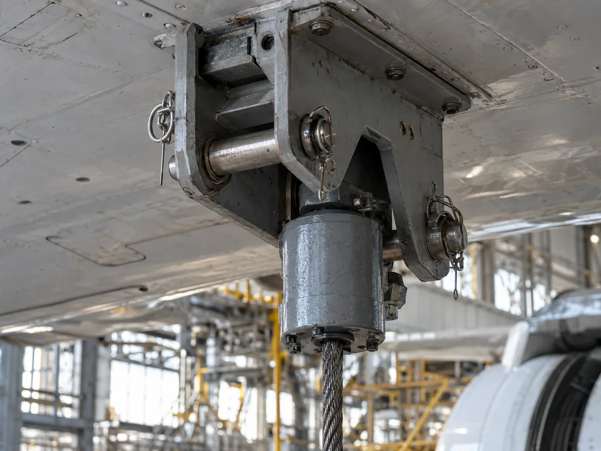
Stand documentation shows that stands handle bootstrap in different ways.
| Stand | Bootstrap provision | Other details listed |
|---|---|---|
| Dedienne CFM56-3 | Bootstrap points on the engine stand trolley | Counterweight to balance weight during bootstrap operation; for the CFM56-3 on Boeing 737-300/400/500 |
| Dedienne CFM56-7B | Bootstrap points on the engine | Interfaces with the Fan Frame and Turbine Rear Frame; 8 shock absorbing mounts between cradle and trolley; for the CFM56-7B on Boeing 737, Boeing AEW&C and Boeing P-8 Poseidon |
| AGSE CFM56-7B (AGSE-E207-G01) | Bootstrap-capable transport stand | Used for bootstrap-style changes at the wing as well as in the shop |
| AGSE/DAE CFM56-3 | Bootstrap capability for on-wing removal and installation | Caster brakes and swivel locks |
| Hydro Basic stands, Trent 1000 and Trent XWB | Bootstrapping kits where specified | Road and sea transport, storage and local movement |
On the Dedienne CFM56-7B stand, the 8 shock absorbing mounts are there to protect engine interfaces from shock, vibration and acceleration during transportation. According to AGSE product literature dated 02-19-26, which lists this under “All Stands” in its CFM56-7B shipping stand section, its CFM56-7B transport stands (AM-2811 cradle, AM-2563 base) support on-wing engine removal and installation through bootstrapping or alternate methods. AGSE also states that “CFM International, GE Aerospace, or Safran Aircraft Engines approves, qualifies, and recommends AGSE GSE & Tooling for safely handling CFM56 engines (except AGSE-Y002).” Dedienne’s CFM56-3 leaflet, dated 05-2022, is headed “FINAL QUALIFICATION PROCESS BY SAFRAN AIRCRAFT ENGINES” for engine removal on aircraft with thrust reverser; the leaflet does not state that the qualification was completed.
Cradle and base design in general is covered in our guide to the aircraft engine cradle and stand base.
The FAA powerplant handbook states that removal and installation procedures usually vary widely with the type of aircraft and engine, so no single list of instructions covers all engines, and it tells technicians to always reference the applicable manufacturer’s instructions before any phase of the work. The handbook chapter describes removal with a sling and hoist in these general steps:
For installation, the stand is moved as close as possible to the nacelle and the hoist takes most of the engine weight before the bolts holding the engine to the stand are removed. The engine must be steadied when the hoist frame moves. While the mount nuts are tightened, the hoist should support the engine weight sufficiently to allow alignment of the bolts; otherwise the nuts can reach torque without holding the engine securely. The handbook is direct about hardware: always use the type of bolt and nut recommended by the manufacturer, and never use an unauthorized substitution. After the nuts are safetied and the sling and hoist are removed, bonding strips are connected across each engine mount.
On mount design, the handbook notes that some mounting systems use two mounts at the forward end and a single mount at the rear. The forward vibration isolator mounts carry vertical, side and axial (thrust) loads and allow for thermal expansion; the aft mounts take only vertical and side loads and accommodate thermal expansion without applying axial loads to the engine flanges. Sling selection and hoisting in more detail are covered in our guide to aircraft engine slings.
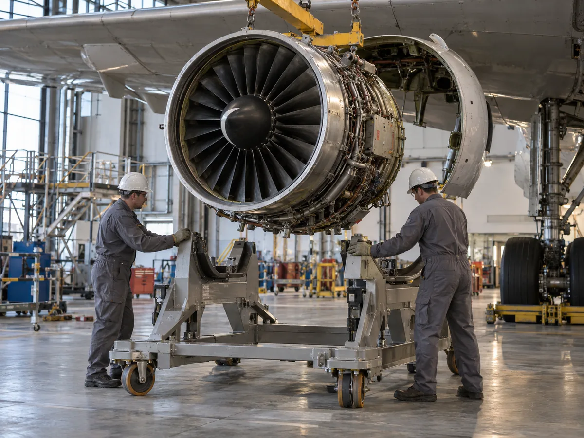
The FAA’s lessons-learned account of the 1979 DC-10 accident describes an engine change done with a procedure the maintenance manual did not approve. The DC-10 maintenance manual instructed that engine and pylon removal be conducted as two separate activities, and removal of the engines and pylons as a unit was not an approved procedure. On the DC-9, an engine change took approximately four hours; on the DC-10 it required approximately 24 hours. American Airlines developed an alternate procedure to save time, and according to the FAA it was not properly validated.
Strut failure was determined to have been caused by structural damage during engine/pylon reinstallation using a forklift. The FAA describes a lack of precision in the forklift, an inability to perform the fine manipulations needed, combined with tight clearances between the pylon flange and the wing clevis. On two Continental DC-10s, in December 1978 and February 1979, the same kind of reinstallation had produced nearly identical damage. AD 80-11-05 R1 required removal and reinstallation of the engine and pylon separately, with inspections before further flight.
Bootstrap beams are not the only way to change an engine on the wing. RH Aero describes its COBRA system, a four-pillar rig, as an OEM-validated alternative to bootstrap beams. According to the manufacturer, operators report up to 70% time saving versus bootstrap methods, and it quotes 1 h 55 m for an A320/CFM56 change and 5 h 30 m for a 777/GE90. These are the manufacturer’s figures, not independent measurements, and the sources we reviewed do not state when a bootstrap kit is the better choice.
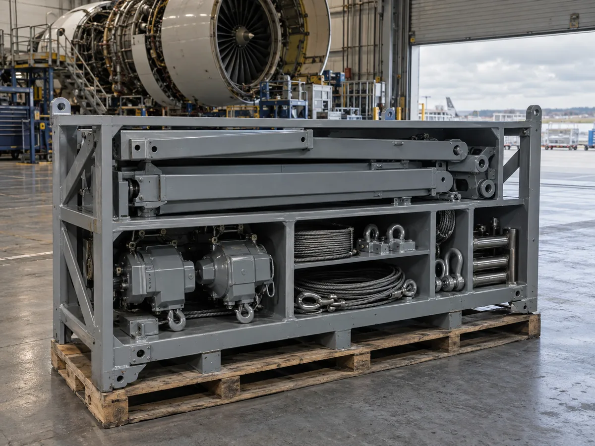
| Kit | Manufacturer | Location |
|---|---|---|
| CFM56-3 Bootstrap Kit | Hydro | Miami, FL |
| CFM56-7B Bootstrap Kit | Hydro | Miami, FL |
| RB211-535 Bootstrap Kit | Dedienne | Miami, FL |
Our kit cards do not list part numbers, load capacity, kit contents or aircraft applicability, and we do not currently list an RB211-535 transport stand. For context on the engine families: GE states that the CFM56 product line powers the Boeing 737 Classic and Next-Generation families, and Rolls-Royce lists the RB211-535E4 for the Boeing 757 family.
Two CFM56 stands from the stand table earlier in this guide, with their listed specifications:
Other CFM56 stands in the fleet include a Frank Brown CFM56-3 stand (Miami, FL and the Netherlands) and CFM56-7B stands from DAE, Dedienne and NextGen.
Planning a CFM56-7B engine change? The CFM56-7B bootstrap kit by Hydro is listed as available in Miami, FL; request a quote on the product page.
In this guide, it means an engine removal or installation done with a bootstrap kit. The AGSE AM-2305 kit, for example, uses four manual chain hoists to raise and lower the engine and cradle to the required positions.
Stands differ. The Dedienne CFM56-3 stand has bootstrap points on its trolley and a counterweight for bootstrap operation, while the Dedienne CFM56-7B stand has the bootstrap points on the engine. The AGSE CFM56-7B stand is listed as bootstrap capable.
Not necessarily. AGSE states that its AM-2305 bootstrap kit for the DC-10 and MD-11 is not designed to be towable, and it ships with reusable shipping containers. Check the documentation of the specific kit before planning how it moves to the aircraft.
According to the FAA lessons-learned account of the 1979 American Airlines Flight 191 accident, AD 80-11-05 R1 required removal and reinstallation of the engine and pylon separately, with certain inspections before further flight after pylon reinstallation. The same account states that strut failure was determined to have been caused by damage during engine/pylon reinstallation using a forklift.
The sources we reviewed do not state an independent comparison. RH Aero claims its COBRA system is up to 70% faster than bootstrap, quoting 1 h 55 m for an A320/CFM56 change, but that is a manufacturer figure.