Aircraft engines

Aircraft engines
An aircraft engine test stand is a ground facility that runs a complete gas turbine engine under its own power while instruments record thrust, temperatures, spool speeds, fuel flow and vibration. Usually called a test cell or test bed, it is where new and freshly overhauled engines prove they meet specification before anyone clears them for flight. It is a different tool from the transport and maintenance stands that carry engines around a shop – two product categories that share a name and almost nothing else.
In a test cell, a complete gas turbine engine is rigged to a thrust frame, started under its own power and taken through its full power range while a sensor network records how it behaves. Engine manufacturers use development test cells to characterize and certify new designs. MRO shops use production test cells to confirm that an engine coming out of overhaul delivers rated thrust, stays inside its temperature limits and shows no abnormal vibration before anyone bolts it back onto a wing.
Flight testing alone cannot do this job – discovering a severe vibration problem at 30,000 feet is an unacceptable risk. Development programs do push engines to their limits on the ground, but an acceptance run after a shop visit is a different exercise: a defined test schedule from the engine maker’s manual, with limits to meet at each step rather than limits to find. In both cases the cell isolates the variables: airflow, fuel temperature, ambient conditions and applied load are all measured or controlled, so every anomaly can be traced to its source.
Two basic layouts exist. Indoor test cells enclose the engine in a hardened chamber with a tuned air inlet and an augmenter exhaust tube, which contains the noise and allows testing in any weather. Outdoor test stands mount the engine on an open thrust frame – simpler and cheaper to build, but hostage to wind and ambient conditions.

The terminology causes real confusion, because “engine stand” covers two entirely different product categories. A test stand runs a live engine and measures its performance. A support stand – transport, shipping, storage or maintenance – holds a non-running engine safely during logistics and shop work, and it never sees an engine start. Buyers searching for one frequently land on the other, so the table below puts the two side by side.
| Feature | Engine test stand (test cell / test bed) | Engine support stand (transport / maintenance) |
|---|---|---|
| Purpose | Run the engine and measure performance | Hold, move, store or service a non-running engine |
| Engine state | Operating, up to full takeoff power | Shut down, often preserved for storage |
| Key hardware | Thrust frame, load cells, data acquisition, fuel and air conditioning | Cradle, base frame, shock mounts, casters, tie-down points |
| Typical location | Dedicated facility at an OEM or engine shop | Hangar floor, truck bed, freighter deck, warehouse |
| Cost scale | Multi-million dollar installation | A fraction of that; commonly rented per project |
If what you actually need is hardware to ship, store or work on an engine, start with our overview of the types of aircraft engine stands used in maintenance and transport – it covers cradles, shock mounts, load ratings and model compatibility. Support stands themselves are one category of aviation ground support equipment – the wider machinery that services aircraft between flights.
Need a CFM56-7B engine stand for shipping or shop handling? National Aero Stands has OEM-compliant stands ready for dispatch.
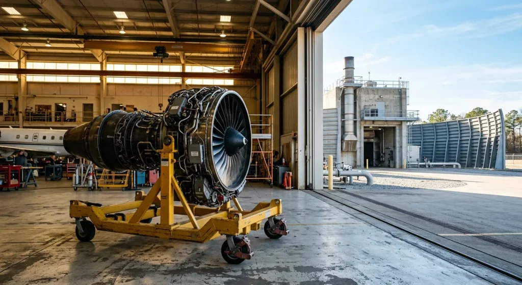
A turbofan or turbojet cell is built around a small set of load-bearing and measurement systems working together:
Turboshaft and turboprop rigs add a second family of hardware, because their output is shaft power rather than pure thrust: dynamometers and torque meters apply and measure rotational load, while gearboxes, inertia flywheels and interconnecting drive shafts link the engine to the measurement train. Multi-faceplate mounting walls let one firewall accept several engine models, which cuts changeover time between test campaigns, and portable test stand builds bring a reduced diagnostic suite directly to the flight line instead of trucking the engine to a stationary laboratory.
A modern acceptance run records every parameter that defines engine health, and the operator compares each reading against limits set by the engine manufacturer. Whether a given engine needs that run at all depends on the work scope: the manufacturer’s approved maintenance data, applied under 14 CFR Part 43, defines which shop visits end in the cell and which do not.
| Parameter group | What is recorded | Why it matters |
|---|---|---|
| Thrust | Force at the thrust frame load cells | Confirms the engine delivers rated takeoff and climb thrust |
| Spool speeds (N1 / N2) | Fan and core rotation speeds | Verifies compressor stages stay within structural margins |
| EGT (exhaust gas temperature) | Turbine exhaust heat and EGT margin | Reveals combustion anomalies and remaining time on wing |
| Fuel flow | Consumption across the power range | Combined with measured thrust, yields specific fuel consumption |
| Oil system | Pressure, temperature, chip detection | Confirms lubrication and flags internal wear debris |
| Vibration | Frequency spectra at multiple engine stations | Detects imbalance and bearing distress before failure |
Vibration analysis is the dataset shops watch most closely in a post-overhaul run: irregular rotational frequencies caught on the ground prevent minor imbalance from growing into blade or bearing damage in service. Development cells go further, using instruments such as laser velocimetry to map internal airflow so designers can refine combustor and turbine geometry for performance and emissions before a design is frozen.
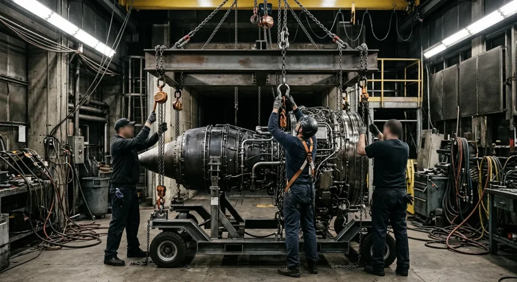
When the engine throttles up, the thrust frame absorbs the longitudinal force and transfers it into calibrated load cells, giving operators a real-time measurement of exactly how much push the engine generates. On shaft-power rigs, closed-loop torque control runs the dynamometer as an automated feedback cycle, continuously adjusting mechanical resistance to imitate real flight profiles without a human hand on the dial.
A GE90-115B pushes on its mounts with over 115,000 lbf at rated power, which is why test cell structures owe more to civil engineering than to shop tooling.
| Engine | Aircraft application | Approx. takeoff thrust |
|---|---|---|
| CFM56-7B | Boeing 737NG | approx. 19,500-27,300 lbf |
| LEAP-1B | Boeing 737 MAX | approx. 23,000-28,000 lbf |
| PW1100G-JM | Airbus A320neo | approx. 24,000-33,000 lbf |
| Trent 800 | Boeing 777 | approx. 75,000-95,000 lbf |
| GE90-115B | Boeing 777-300ER | approx. 115,000 lbf rated; over 127,000 lbf recorded during testing |
Ratings are approximate takeoff figures; the engine makers publish the canonical numbers – the Pratt & Whitney GTF pages carry the PW1100G-JM data, for example.
Throttle inputs come from a remote operator station that replicates cockpit commands while keeping engineers shielded from noise and jet blast. Military test programs go further and mirror actual flight hardware: cells built for fighter engines integrate cockpit-style throttle logic, and engines with thrust vectoring nozzles need the console to command and validate multi-axis nozzle movement alongside standard acceleration and deceleration profiles.
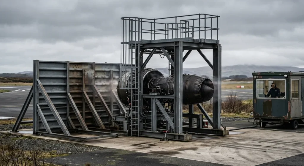
A thrust reading taken on a humid summer afternoon and one taken on a freezing morning describe two different engines until both are corrected to reference conditions. Media conditioning systems manage the fluids and air the engine receives, so a change in the readings reflects the engine itself, not the weather outside.
Fuel and oil circuits filter their fluids and hold them at defined temperatures, preventing thermal shock at start and stabilizing pressures at maximum load. Some facilities add dedicated cooling circuits to protect structural elements during extended runs. On the air side, intake conditioning regulates the temperature and humidity of the flow entering the compressor – chilling it to represent a winter high-altitude airport or heating it to simulate a desert runway. Specialized altitude test facilities control pressure on both the inlet and the exhaust side to reproduce cruise and climb conditions without leaving the ground.
Safety design in a test facility starts from the assumption that the engine on the frame may fail at full power. Personnel operate from a separate hardened control room. Inlet screens keep foreign objects out of the fan. Automatic shutdown logic trips the engine the instant a monitored parameter – overspeed, EGT, oil pressure, vibration – crosses its limit, far faster than a human could react. Closed-loop load control prevents sudden structural over-stressing during rapid load changes. And during rigging, before the engine ever reaches the thrust frame, padded support equipment and correct cradle adapters protect the engine exterior from contact damage.
Engine OEMs operate their own development and production cells – GE Aerospace, for example, tests military and smaller commercial engines at its Lynn, Massachusetts plant. Large MRO providers and airlines, typically repair stations certificated under 14 CFR Part 145, operate acceptance cells correlated against an OEM reference cell, so their results are accepted for return-to-service decisions. And specialist engineering firms design and build cells, thrust frames and data systems for customers who need their own capability.
An organization weighing a purchase against an in-house build is choosing between a certified turnkey system with manufacturer support and a custom design for specialized research. Commissioning decides whether either investment pays off. Fluid lines, sensor networks and structural mounts are calibrated one by one, operators train on test and emergency procedures, and then the cell runs a known engine so its numbers can be checked against an OEM reference. Until that correlation is signed off, the cell produces figures nobody can certify against.
Transport and maintenance stands follow the opposite economics: rented far more often than bought. National Aero Stands supplies aircraft engine stands for rent and lease across the CFM56, LEAP, Trent, GE90 and PW families – the hardware an engine rides on before and after its trip to the test cell. Getting the engine to the cell and back – by air-ride trailer or freighter – is covered in our aircraft engine transportation guide.
Key takeaways
Is an engine test stand the same as an engine stand?
No. An engine test stand (test cell) is a facility that runs a live engine and measures its performance. An “engine stand” in MRO usage is support tooling – a cradle and base frame that holds a shut-down engine for transport, storage or maintenance. If the engine will be running, you need the facility; for shipping, storage or shop work you need the support stand – and only the support stand is the kind of hardware you can rent for a project. What does a jet engine test cell measure?
A test cell records thrust via load cells, fan and core spool speeds (N1/N2), exhaust gas temperature and EGT margin, fuel flow, oil pressure and temperature, and vibration spectra. Operators compare every value against engine manufacturer limits to confirm the engine performs to specification before it is released for flight. Why are engines tested after overhaul?
An acceptance test run proves that the rebuilt engine delivers rated thrust, stays within temperature limits and shows no abnormal vibration. Whether a full test cell run is required depends on the scope of work and the engine manufacturer’s approved maintenance data rather than a blanket regulation. When it is required, the ground run finds problems that would be dangerous and far more expensive to discover in flight. How is thrust measured on a test stand?
The engine is mounted to a thrust frame that absorbs its longitudinal force. Calibrated load cells between the frame and the cell structure convert that force into a precise reading, logged in real time across the whole power range. Turboshaft and turboprop engines are measured differently, with dynamometers and torque meters on the output shaft. Can any test cell run any engine?
No. Each cell has thrust, airflow and dimensional limits, plus engine-specific mounting adapters and instrumentation. A cell must also be correlated for a given engine type – checked against an OEM reference – before its results count toward certification. Multi-faceplate mounting walls help one cell cover several related engine models.